AB INITIO
| Back |
|---|
An inductor is an electronic component with the property of inductance. All conductors have inductance between their ends but the term inductor is usually reserved for a component which has an artificially increased inductance compared to a straight wire. This may be implemented in several ways including curling the wire into a coil, surrounding the wire by a ferro-magnetic sleeve, or winding the coil on a ferro-magnetic core. But first we must understand a few things about inductance.
Basic Theory
Inductance is a difficult concept because it uses quantities and units which are not common every day terms such as Volts, Amps and Watts. We will start with the fundamentals: Electric current in a wire, (symbol I), always surrounds itself with a magnetic field, (H), which is proportional to the current. As in the case of Ohm’s Law, where Volts working against resistance, causes a current to flow, so here, magnetic field, working against magnetic resistance, causes a Magnetic Flux, F, to flow. Magnetic field is measured in units of “Amps per metre”, (A.m-1), magnetic resistance is usually defined in terms of its inverse, magnetic permeability, µ, and magnetic flux is measured in Webers, (symbol Wb). The intensity or density of magnetic flux, B, is measured in Webers per square metre, (Wb.m-2). The Weber per square metre is given a new name, the “Tesla”.
Hence we have a sort of analogue of Ohm’s Law connecting these quantities:-
B = µ × H
Magnetic permeability, µ, therefore has the units of Wb.m-2/A.m-1 = Wb.A-1.m-1
The total magnetic flux, F, depends on the product of the current, I, and a factor dependent on the geometry and environment of the wire, L. So we can write:-
F = L × I
The factor, L, is a sort of “figure of merit for magnetic flux”, and is measured in Webers per Amp. This figure of merit is called “Inductance” and the unit, “Webers per Amp” is given the separate name, “Henry”, symbol H. (The unit Henry, H, must not be confused with the commonly used symbol for magnetic field, also H, which is measured in Amps/metre). It can now be seen that permeability, µ, can also be expressed as Henrys per metre, (H.m-1).
In Practice
So much for the theory connecting all these strange terms. The commonest geometry referred to above for increasing the inductance of a wire involves curling the wire into a coil so that the magnetic field resulting from the current effectively couples to the wire many times. The magnetic field and flux is therefore equivalent to many wires each carrying the same current. The magnetic flux from the wires links with the wires each time they pass the reference point, resulting in the inductance, (L in Henrys), being proportional to the square of the number of turns of wire. Other methods for increasing inductance include embedding the wire in, or threading it through, a material of different permeability, µ, from air. For convenience, permeability, µ, is separated into the product of µ0, the permeability of free space, (4 ??10-7 H.m-1), and µm a simple numerical factor describing a “figure of merit” for the material surrounding the wire, such as air, (1) or iron, (in the order of 1000).
Inductors have another vitally important property apart from increasing magnetic flux per Amp, and this depends upon Maxwell’s equations, and in particular upon the one stating: “A changing magnetic field generates an electric field”. From this is derived “Lenz’s Law”, which states that “a changing current through an inductor produces a changing magnetic field which tends to induce a current in a direction opposing the original change in current”. Thus, an inductor offers an “impedance” to a change in current through it. As the rate of change in current is proportional to the frequency of the current through the inductor, the higher the frequency for a given inductance, the greater the impedance. This important fact is often made use of to filter out Radio Frequencies from DC and lower frequencies in radio science.
The use of iron to greatly increase the inductance of a coil has its limitations, as iron is not only a magnetic material but is also a moderately good conductor. Currents can therefore also be induced in the iron. These unwanted currents, called “eddy currents”, flowing through the resistance of the iron, heat it and lead to power loss in the inductor. The eddy current loss can be ameliorated by dividing up the iron making up the core of a coil into thin insulated slices or laminations perpendicular to the direction of the eddy currents, and this is effective up to several 10s of kHz. Another similar technique is to use fine iron dust set in a plastic or a fired clay mix, and this is suitable for use up to the low MHz range. However, at higher frequencies, up to 100s of MHz, ferrite, which is a ceramic magnetic insulator is used. Another potential problem which must be taken into account when using iron or ferrite to increase inductance is that its permeability, µ, is only constant at low flux levels. At higher flux levels it “saturates” and its permeability falls.
Lenz’s Law, described above, applies equally well to a separate coil tightly magnetically coupled to the first. Here also a current can be induced, and this is the basis of the “Transformer”, which is another subject.
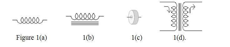
The circuit symbols for an air cored inductor, a ferro-magnetic cored inductor, a ferrite ring or bead on a wire, and an iron cored transformer are shown in figures 1(a), (b), (c) and (d) respectively.
The above reasoning which was applied to loss in core materials applies to both mains and audio transformers which tend to have their cores made out of laminated iron. Transformers in switched mode power supplies, operating at 10s of kHz, and inductors for VHF usually have their cores made of an iron dust mixture or ferrite. Inductors and transformers operating at UHF and beyond tend to have air cores. Unfortunately, a really low loss magnetic material of high permeability has yet to be developed although some progress has been made in recent years.
Small wire ended inductors, intended for use at radio frequencies, are often colour coded rather like resistors with two adjacent spots or rings indicating digits and the third indicating a multiplier, the total figure showing inductance in micro-henries. However colour coding of inductors is less reliable than for resistors and it is advisable to measure an inductor before replacing or inserting one in a circuit.
| Back |
|---|
PRAECEPTOR