Power at the higher frequencies Part ll
| Back |
|---|
In a previous article, we looked at the first generators of “higher frequencies” such as the B-K Oscillator and the klystron. These turned the apparent disadvantage of the electron transit time in a vacuum being comparable to the period of the Radio Frequency, into an advantage. This was done by using velocity modulation of the electron stream instead of amplitude modulation. The transit time of the electrons during a “drift space” then turned velocity modulation into electron density modulation. The input and output devices could thus be separated by a far greater distance than that between the grid and anode of a triode valve.
One of the devices which had been looked at in the decade prior to World War ll and which had initially shown promise was the split anode magnetron. This was a slightly odd device in which an electric field was used to accelerate the electrons and a transverse magnetic field was used to inject a component of negative resistance. However, under the pressures of the war, a microwave generator of hundreds rather than a few watts of RF power was required for urgent radar applications. Research was therefore continued, initially mainly at Birmingham University, and it is worth describing the mechanism and evolution of this odd device.
The Split Anode Magnetron
It had been well known since J.J. Thomson’s experiments in 1897 that a stream of electrons in a vacuum could be deflected into an arc of a circle by a magnetic field. The magnetic field had to be applied at right angles to the path of the electrons. In a basic diode consisting of a hot filament wire at the centre of, and coaxial with, a metal cylinder at a positive voltage to that of the filament, the path of the electrons in the absence of a magnetic field is as shown in figure 1a. However, the presence of an axial magnetic field bends the electron path and increases the transit time as shown in figure 1b.
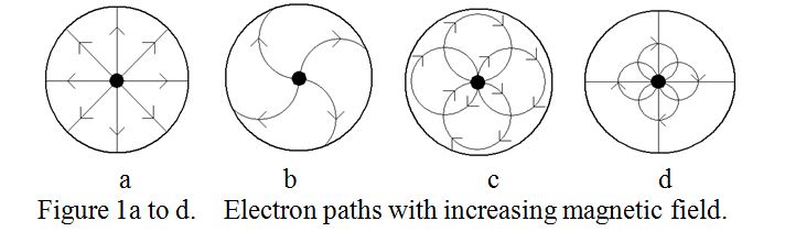
A further increase in magnetic field “cuts off” the electron current as shown in figures 1c and 1d. Use was made of the curved path to produce negative resistance by splitting the anode as shown in the fragment of circuit shown in figure 2.
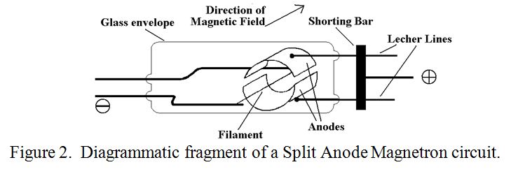
The operation may be explained by the following rough description. The RF output builds up from noise as in any oscillator. Both anodes have the same average DC voltage, but due to random noise, let us assume one anode is slightly more positive than the other. As a result of the curved path, some of the electrons, although accelerating towards the more positive anode, finish up at the less positive (or RF more negative) one. I.e. some electrons are fooled into going to the wrong anode. Electrons being forced to go to the more negative anode corresponds to a component of negative resistance in the RF circuit. The electrons forced to arrive at the more negative anode become decelerated by the decelerating field and give up their energy to the tuned circuit, (in this case a Lecher Line). (As explained in a previous article, a Lecher Line is a parallel wire transmission line comprising a pair of closely spaced bare wires which can be bridged by, for example, a short circuit, a small filament lamp bulb, or a neon tube, for demonstrating the presence of RF power). The efficiency of the split anode magnetron, (measured as the RF power out divided by the DC power in), can be increased by increasing the magnetic field well beyond cut-off and increasing the anode voltage to restore operation. This is somewhat analogous to “Class C” operation in a valve or transistor power amplifier. However, efficiencies of only a few per cent and powers of only a few watts were achieved.
The Cavity Magnetron.
Such was the state when John Randall and Harry Boot of Birmingham University made their dramatic breakthrough in 1940. At that time British Radar was “crying out” for a centimetric wavelength transmitter capable of producing more than a few watts of RF power. What Randall and Boot did was to make an all metal device from a billet of copper, initially with six identical cavities surrounding a central hot cathode. Figure 3 shows the general form. The magnetic field was applied along the axis of the cathode as in the split anode magnetron.
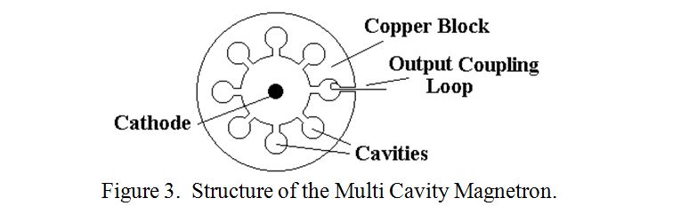
The cavities were designed to resonate at a wavelength of 10cm. This was achieved within a couple of percent. Bunching of the electrons occurs as in a klystron by the RF electric field across the mouths of the cavities. As a result the electrons bunch into “spokes” as in a wheel with half the number of spokes that there are cavities. The electron “space-charge wheel” rotates at a rate of two cavities per cycle. Those electrons which are accelerated by the field from an adjacent cavity take energy from the RF circuit and continue to pass other cavities to which they may eventually give up their energy. Those which are decelerated by the field give up their kinetic energy to the RF circuit and are soon collected by the positive anode and removed from the population. (It has been said that the phyisics of electromagnetic wave formation inside the cavity magnetron cavities is amongst the most complicated areas of classical physics, both from theorectical and practical viewpoints).
The RF output connection of the original device was a small loop of wire inside one of the cavities which was connected to a Lecher Line. It was found to produce copious amounts of RF power at a DC to RF efficiency of about 30%. Moreover, the more power that Randall and Boot fed in, the more the RF output. During one experimental session they burnt out about a dozen Car headlamp bulbs. They estimated the output at “well in excess of 100W CW”. At a meeting with the Air Ministry later that week they were urged to concentrate on “Pulsed Power”, and after some further work on the cathode, the initial specification of a peak power of 25kW was exceeded. The rest, as they say, is history. However there was a problem in applying the new device to Radar. The output power varied a little from pulse to pulse and so did its frequency, and it was soon realised that multiple cavities coupled together have several modes of resonance. The desirable mode, (but not the one occurring every time at switch-on), was one in which neighbouring sectors between adjacent cavities were in anti-phase. This problem of “wrong modes” was eventually overcome by another inspirational idea, by J. Sayers of GEC Research, of connecting “alternate but one” sectors by thick conductors outside the electron interaction area. This was known as “strapping” and it was found to also greatly increase the DC to RF efficiency, A number of other variants have since been developed for stabilising the output power and frequency of the multi-cavity magnetron. There have also been a number of variants in the shape of the cavities, mainly to ease manufacturing problems. The large scale manufacture of cavity magnetrons during World War ll was largely handed over to the Americans and Canadians, following the mission by Sir Henry Tizard in which he exchanged British know-how for American manufacturing capability. The Americans were mightily impressed by the British achievement. In fact President Roosevelt described the magnetron as “the most important cargo ever brought to American shores”. Historically, it had a huge influence on the accuracy of the bombing campaign and on the anti-submarine war against Germany during World War ll. Modern magnetrons, and a related device, the amplitron, are capable of producing many kilowatts of mean power and many megawatts of peak power at centimetric wavelengths.
Apart from its use in small and medium size “non coherent” radars, the main application of the cavity magnetron these days is in the CW mode, at a power of about 1kW, and a wavelength of about 12cm for heating food in microwave ovens. However, in February 1990, 50 years to the day from the first successful operation of the cavity magnetron, a small re-union and silver jubilee celebration was held at Birmingham University, some of it in the original building where the cavity magnetron was developed, and I was privileged to be invited. Here one could circulate among “the greats” and the survivors of the original team and hear their stories.
PRAECEPTOR
| Back |
|---|