| Back |
|---|
The RF Unit
This is the really the heart of the system, be it Marconi style spark transmitter or Tesla coil; it magically turns pulses of current into RF at MHz frequencies. (See the circuit diagram of figure 1 in part 1 and the photo of figure 3).
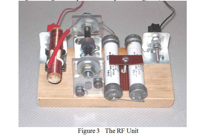
From left to right in the photo can be seen: an isolating choke, the RF unit spark gap, (consisting of two carrage bolts with their domed heads a few mm apart and mounted on perspex uprights), and two white cylindrical high voltage capacitors connected in series. The spark gap of the RF unit is set to arc across at about 5kV, a slightly lower voltage than the switch unit’s safety gap. The gap actually behaves like a voltage sensitive switch. Below 5kV the spark gap is open, and above 5kV it is closed as a result of ionisation and only offers a resistance of a few Ohms. It does this 100 times per second, 50 times on positive half cycles and 50 times on negative half cycles of the “stepped up” mains supply. Thus, the 0.0025µF capacitor charges up to 5kV and discharges into the pan wound primary of the Tesla coil unit 100 times per second.
The Tesla Coil Unit
This comprises a pan wound primary coil of up to 8 turns, (the turns of which can easily be tapped using a “crock-clip”). The resonant frequency is determined by its inductance and the 2.5 nF capacitance. This coil is loosely coupled to the secondary coil of about 700 turns wound as a single layer extending from the base plate upwards for 11 inches. It is brought to the same resonant frequency as the primary coil by means of the self capacity of the metal ring or toroid at its top. This has gentle curvature and no sharp edges so as to avoid corona discharge from its surface. At its centre, and connected to it, is an upward pointing metal nail from the point of which the corona discharge is intended to occur. See Figure 4.
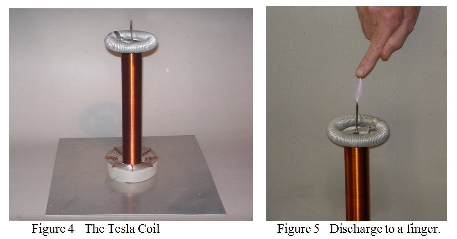
This “Top Hat” capacitor was made from a short length of electrical flexible metal conduit bent into a circle.
When the system is switched on, and in only a slightly darkenned room, a spectacular corona discharge can be seen originating from the pointed end of the nail. This discharge extends for several inches into the air, accompanied by a clearly audible crackling noise. As the pulses are at radio frequency, (about 2 MHz), and at very high impedance, (Voltage estimated at about 150kV and current a few microamps), the discharge may be safely drawn off to a finger as shown in figure 5. The tiny current involved then passes to earth over the surface of the skin with only a modest sensation. There is some sensation however, but I believe this is more to do with the explosive effect of the expanding air caused by each discharge than any purely electrical effect.
In the fourth and last part of this article I shall describe the operation of the Tesla Coil in more detail and my attempts to measure how well simple sparks generate radio frequency power.
| Back |
|---|
John, G0NVZ