| Back |
|---|
Part I Recap on Single Wire Antennas.
In general, at any given frequency, a wire has both inductance and capacitance. Starting with a very short wire, both inductance and capacitance initially increase as the wire is made longer. I.e., the magnitude of the inductive reactance, (which is positive), increases and the magnitude of the capacitive reactance (which is negative), decreases. When the magnitude of the inductive reactance becomes numerically equal to that of the capacitive reactance, (one being positive and the other negative), they cancel each other out and the wire is said to be resonant at that frequency, and it then only has resistance The first time resonance occurs is when the wire is approximately half a wavelength long. It occurs again and again when the wire is two halves, three halves etc. wavelengths long. If this resonant wire is “broken” anywhere and the two parts supplied in anti-phase with RF from a suitable generator, then the wire will radiate and will load the generator with a pure resistance whose value depends upon where the wire is broken. One of the characteristics of a radiating resonant wire is that it will have a “Standing Wave” on it with voltage and current maxima and minima. The ratio of Voltage to current at any point along the wire is the effective resistance at that point, (not neccessarily the radiation resistance which is defined later). The value of the resistance where the wire is broken is highest at the voltage maxima, (one of which will be at the end of the wire), where the resistance may reach several thousand Ohms, and it is lowest at the current maxima where the resistance may be tens of Ohms or in some cases much less. The value of resistance at the current maxima is known as “The Radiation Resistance”. If the wire is only one half a wavelength long then when it is broken at its centre to make the feed point, (the current maximum), the resistance is about 72 Ohms. Of course, the feed point may be anywhere between its centre and its end and the feed point resistance rises rapidly from 72 Ohms for centre feeding to about 5000 Ohms for end feeding. In practice end feeding a truly isolated wire is difficult. Another useful position for the feed point of a wire one or more half wavelengths long is one third of the way from one end where the impedance is about 300 Ohms, which is a common twin wire feeder impedance. This variation in impedance, (from low at a current maximum to high at a voltage maximum), can be exploited by using the resonant wire as a transformer whose ratio can be varied simply by tapping in at a suitable point between a current maximum and a voltage maximum.
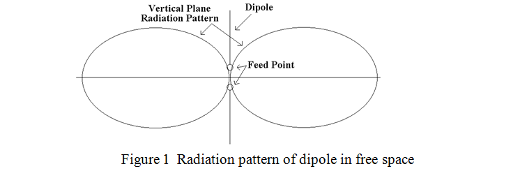
A representation of a half wave dipole in free space, together with its radiation pattern in the plane of the dipole is shown in figure 1. (The current maximum and feed point are in the centre). The radiation pattern in the plane at right angles to the plane containing the dipole is a circle, i.e. the dipole radiates equally in all directions.
If the wire is two half wavelengths long, then the resistance at either of the two current maxima is about 80 Ohms instead of 72 Ohms. For three half wavelengths it is about 90 Ohms. As the wire length is further increased, the resistance at the current maxima rises and the resistance at the voltage maxima falls until, for an infinitely long wire, they both converge to a value of about 500 Ohms. The exact value of this convergence impedance depends on the wire diameter and the proximity of earth and the antenna appears to the generator as a long lossy transmission line of this impedance. (I.e., a load of 500 Ohms). That is why, when you try to use your long, random length wire, (usually reserved for short wave listening), as the antenna for your 70 cm transceiver, (which is designed to work into a 50 Ohm load), you can still make most of your usual local contacts but the VSWR is about 10:1. (The Standing Wave Ratio is roughly the ratio of the transmission line impedance to the load impedance at the end of the line, assuming a resistive load).
Part II Halving the length and tuning against ground.
At first sight there seems to be a similar important set of cases to those where resonant wires are multiples of a half wavelengths long, where the wire length is only half those lengths, i.e., where the wire is a quarter, two quarters, three quarters etc. of a wavelength long and is tuned against ground. However these cases are not really an additional and separate set, but are something of an illusion. What happens is that the anti-phase current from the generator, instead of flowing into the other “half” of the wire, flows into the ground which then forms an image of the real wire antenna, rather as a pencil held vertically in contact with a horizontal mirror forms an upside-down image of itself. This is represented, together with the vertical plane radiation pattern for a vertical, quarter wave wire or “whip” antenna, in figure 2 below.
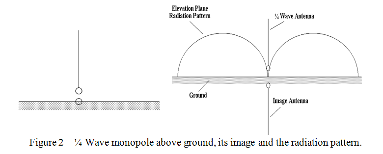
It is seen that the radiation pattern is then just the upper half of that of the “full” half wave dipole in free space. The feed point impedance, (radiation resistance in this case), is also half that at the centre of a “full” half wave dipole, i.e., it is 36 Ohms instead of 72 Ohms
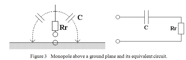
If the length of a dipole is made shorter than a half wavelength, (or the length of the monopole above a ground plane is made shorter than a quarter wavelength), the radiation resistance falls rapidly and is no longer purely resistive. In fact the radiation resistance becomes proportional to the square of the length in both cases and appears in series with a capacitance which depends on the length and thickness of the wire(s). (A typical capacitance for thin aerial wires is about 5 pF per metre length). For example, the radiation resistance of an eighth wavelength wire “tuned against a ground plane” is just 6 Ohms. Remember, the radiation resistance of the “two armed” dipole is always twice that of the monopole above its ground plane. Radiation resistance is the only “useful” thing about an aerial and with such low values, care must be taken to make any other loss resistance in series with it as small as possible if the aerial is to remain efficient. A physical representation and the equivalent circuit of a monopole above a ground plane is shown in figure 3, where the dotted lines represent the capacitance of the aerial wire to ground.
Because the useful radiation resistance of a short antenna is in series with a capacitance, an inductance must be added in series which just cancels the capacitive reactance to make the antenna system look resistive to the generator. This inductance often takes the form of a “loading coil” either near the centre or near the base of the antenna wire or rod. A base loading coil for VHF antennas can sometimes be seen as a “spring” between the whip and the roof mounting on taxi-cabs and police cars. Unfortunately, the inductance, though necessary, also has resistance.
From all this we can see why a good earth is so important when using an antenna significantly shorter than a quarter wavelength. Any earth resistance is effectively in series with the radiation resistance and can quite easily dominate it. On transmission this means that most of your power goes into warming up the earth rather than being radiated. It doesn’t matter so much on reception, (where atmospheric noise is the main competitor to the wanted signal), as any loss in antenna efficiency attenuates both the noise and the signal equally.
Unfortunately, typical amateur radio “earth rods” consisting of a length of scaffold pipe driven five or six feet into the sort of earth around St. Albans usually have a “resistance to earth” of some tens or Ohms. In the early days of radio, about the time when crystal sets were in vogue, enthusiasts used to pour a solution of Glauber’s salt, (hydrated sodium sulphate), around their earth rods to lower their resistance to earth. This is said to last for several years before being washed out by rain fall.
| Back |
|---|
John, G0NVZ