The main initial problem in making use of these newly discovered waves for “wireless” communication was generating and receiving them efficiently, and this mainly revolved around improving the sensitivity of the receiver. Many systems were tried and claims made and many patents were filed, for the gradual evolution of a workable wireless telegraph system was not a smooth process conducted by team of patient scientists. It was often a scramble, with much hostility, in many cases by charlatans, to corner what promised to be a lucrative market. There were electrolytic and thermo-electric detectors, those that relied on magnetic saturation, and various non linear devices like rectifiers, though these were hopelessly inefficient compared with the modern rectifier diode.
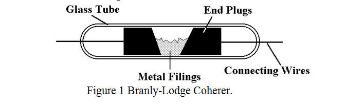
The first real breakthrough, (though they didn’t realise it at the time), came in 1895 from a Frenchman, Professor Edouard Branly and an Italian, Professor Calzecci Onesti, working independently. They discovered that a loose collection of metal filings normally did not conduct electricity, but when they had been subjected to wireless waves produced by an electric spark, they could conduct well until they were shaken or stirred, when again they became non conducting. This device was first improved by the British scientist Oliver Lodge, and he named it a “Coherer”, as he believed that the particles cohered under the influence of wireless waves. This first efficient device for the detection of radio waves is now generally known as the “Branly-Lodge Coherer” to distinguish it from later more efficient types. A representation is shown in Figure 1.
There is still some controversy as to how the device works. One theory was that it was based on electrostatic attraction, another that microscopic welds occurred between the particles. Modern experience with MOSFETs suggests that the oxide or other very thin insulating layer covering the metal particles breaks down at a certain voltage enabling the particles to come into contact.
Whatever the mechanism, about a year ago I decided to make such a device and measure its properties experimentally. The patents on the original device describe ordinary Soda glass with platinum wires sealed into it. The original device was sometimes partially evacuated, but for convenience of trying different fillings and for cheapness, I used ¼ inch ID polythene tube with brass end plugs. The first thing for a would-be experimenter to be aware of is that the common description of “a glass tube filled with iron filings” is misleading. I found that iron was the worst of all the filings I tried. They work on the day that the iron is filed, but progressively deteriorate thereafter. The original literature describes “a small quantity of nickel filings, to which were added a small percentage of silver filings, lying between silver electrodes”. The nearest I could come to this was cupro-nickel obtained by filing an old 50p piece. I tried fine filings and more coarse filings. I also used cylindrical end plugs turned down to tightly fit the polythene tube rather than the tapered ones advocated in the original description of the more sensitive devices. I also tried different distances between the end plugs. I measured the DC resistance after shaking the tube and then applied a steadily increasing voltage until suddenly the resistance fell to a low value which I again measured. The results were moderately repeatable and in summary were as follows.
With cupro-nickel filings and end plug spacing ½ inch, the pre breakdown resistance of 300kΩ, fell, after breakdown, to 100Ω. As the distance between the end plugs was reduced, both the pre and post breakdown resistances fell but the ratio remained approximately constant. Marconi talks about “finely sieved filings”. I didn’t sieve mine but collected them straight off the file. I got the impression that coarse filings worked better than fine ones. Brass filings gave the lowest resistance of those I tried. Lowest resistance of all was from the tiny brass turnings, (really more like tiny chippings), that you get from turning hard brass on a lathe. These produced a “post breakdown” resistance of about 5Ω compared with a “Pre breakdown” resistance of 50kΩ. The sensitivity as a pure “Voltage detector” at DC was pretty terrible, needing about 10 to 15 Volts to produce the low resistance state, though as explained later, there is reason to believe that the sensitivity to RF is better.
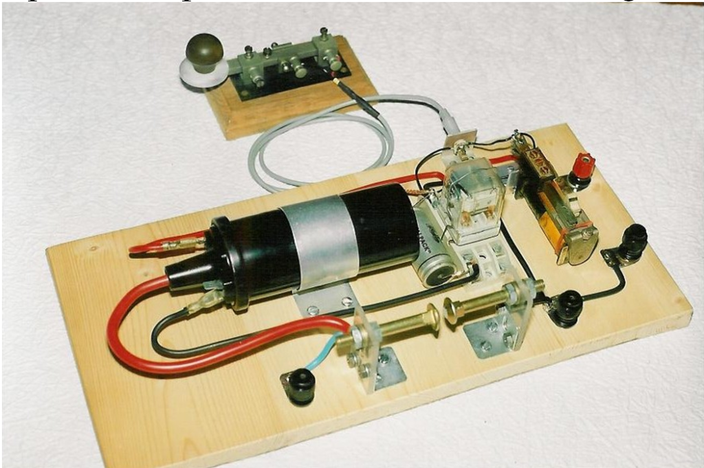
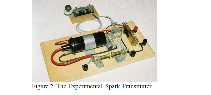
The next stage in my investigation, using the above knowledge, was to build a simple spark transmitter and coherer receiver. I wasn’t going to put my transmitter on the air and therefore I didn’t need the prodigious volts and power of the early Rhumkorff coils. I settled for a 12 Volt car ignition coil, and to get repetitive sparks, I used two relays, one rather delicate one as a buzzer and the second, operated through the current contacts of the first, to interrupt the 8 Amps primary current of the ignition coil. A photograph of the spark transmitter is shown in figure 2.
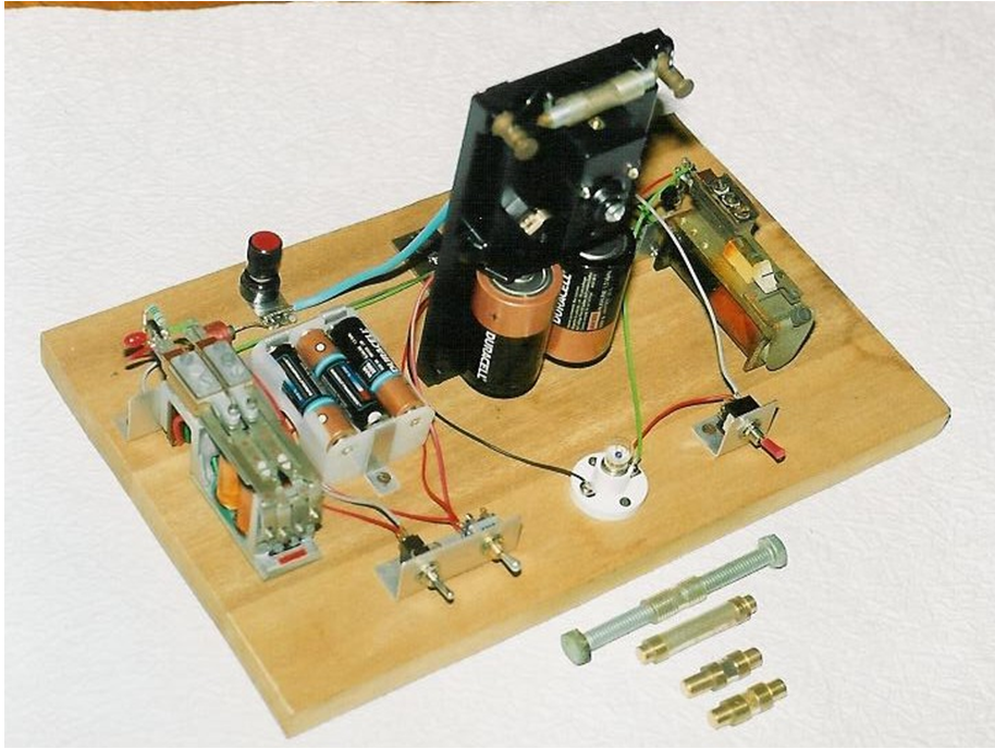
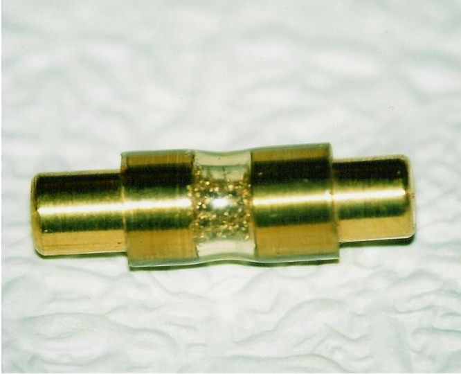
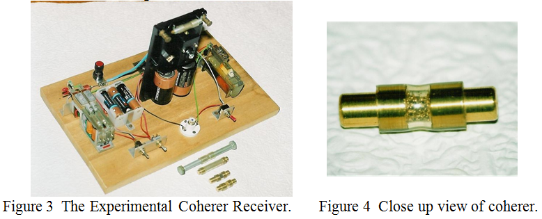
One of the problems with a Branly Lodge coherer is that it is not self restoring. Once it has been switched into the low resistance state by a small voltage pulse, it remains there until shaken or tapped. Lodge used a clockwork tapper to continually tap the glass tube and Marconi used an electric tapper based on an electric bell to give a single tap whenever the resistance of the coherer fell sufficiently to pass current from a single cell to the solenoid of the tapper. I opted for the Marconi system using the mechanism from a modern electric bell, but using a sensitive relay to detect current through the coherer. A second relay them operated a torch lamp bulb to register the signal. A photograph of the home made coherer receiver is shown in figure 3, together with some experimental coherers, and a close up view of one of the coherers is shown in figure 4.
With about 2 foot of aerial on the receiver and no aerial on the transmitter, the reliable range was only about 3 yards. Using a 1M Ohm, times 10 probe on a ’scope, I attempted to measure the minimum peak volts across the coherer required to light the lamp. The measurements were not very precise, but I got the impression that the coherer was rather more sensitive to RF than to DC, which I thought might have something to do with the capacitance between the metal particles in the pre-breakdown state. I then tried to measure the capacitance in the pre-breakdown state. The most sensitive range on my capacitance meter is a FSD of 100 pF, so again my results are not very precise but the capacity across the coherer was certainly less than 1 pF.
In the next part, I will describe other types of coherer, (although I have not experimented with these), and discus the merits of tuned versus untuned systems.
| Back |
|---|
John, G0NVZ