| Back |
|---|
In aerial technology, it is often stated that the effect of the nearby earth, (or ground), should always be taken into account because the earth forms an “anti-phase image” of the aerial the same distance below the ground as the aerial is above it. (In this context, “earth” and “ground” are synonymous). How is this image formed and what effect does it have? It must be stressed that the following is a theoretical treatment and, except where stated otherwise, the ground is considered a perfect conductor. In practice the ground has both resistive and dielectric properties and except where an extensive conducting earth mat is laid around the antenna, it can be far from perfect.
A simple aerial
A quick recap on the physics: electric charge, measured in Coulombs, is the surplus or deficiency of electrons in a body. Electrons all repel each other, and their outward pressure gives rise to Voltage. A charge is always surrounded by an electric field emanating from the charge. The movement of charge is called a current, which always surrounds itself with a magnetic field. In a staight conductor, this is of cylindrical form with the current along the axis of the cylinder. The acceleration of charge always gives rise to electro-magnetic radiation which propagates in a direction perpendicular to the acceleration.
In an aerial, a simple dipole for example, the electrons surge from one end of the aerial to the other. As they approach one end, they get squashed together and their mutual repulsion, (or compression), eventually leads to their reversing the compression process, and they then expand towards the other end of the dipole. If it weren’t for the damping effect of radiation they would oscillate backwards and forwards for ever, rather as a pendulum would go on swinging if it weren’t for air resistance and friction in its pivot. At a particular instant in time the dipole could be envisaged as having a positive charge at one end and a negative charge at the other as indicated in figure 1.

The small circles at the centre represent the feed points. In this treatment, these can be imagined as short circuited so that charge “bounces” from one end to the other.
Isolated charge
As stated above, electric charge has emanating from it an electric field, which is usually envisioned as “lines of force” equally spaced from the charge and dispersing into space. The strength of the field is usually represented by the closeness of the lines in any region. When the charge is brought near a conducting object, some of the electric field lines anchor themselves onto the object at 90 degrees to the object. A charge near a conducting sheet or a ground plane, together with the resulting field lines is depicted in figure 2.
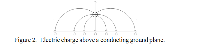
The charge, shown as positive, attracts negative charges, (electrons), from elsewhere in the ground plane to positions just under the surface as shown. Their distribution ranges from high at the nearest point under the charge, to relatively low at a distance, as also indicated in the diagram. This distribution is exactly the same as if a negative charge had been placed below the ground plane at the same distance as the positive charge was placed above it. This is the justification for the imaginary image of opposite polarity below the conducting ground plane.
Aerials and Earth
In the case of a horizontal dipole at an instant in time above a ground plane, it and its image can be represented as shown in figure 3.
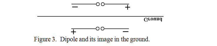
An observer, standing on the ground in a position where the maximum signal would normally be expected to be received, would receive nothing, as the signal from the dipole and its image would be equal and in anti-phase. I.e. there is a null in the vertical radiation pattern at ground level.
In the case of a vertical dipole at an instant in time above a ground plane, it and its image would be as shown in figure 4.
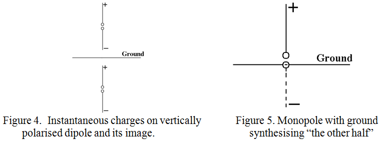
An observer with a receiver standing anywhere on the ground would receive the two waves from the dipole and its image in phase. In fact, even a single “half dipole” or monopole could be used to radiate effectively, the other half of the dipole being “synthesised” by the antiphase image in the ground as shown in figure 5. This forms the basis of the monopole “Tuned against ground”. Although an unbalanced system such as this would seem ideal for connecting unbalanced co-ax directly to it, with the co-ax inner connected to the monopole and the braid connected to an earth spike, the impedance at the input is theoretically half that of a full dipole. I.e. the impedance at the base of a quarter wave monopole is 36 Ω instead of 72 Ω at the centre of a dipole so a similar mismatch of about 1.5:1 would be incurred when conventional 50 Ω co-ax is used.
Radiation considerations of the Monopole
The usual representation of a vertical monopole and a perfect ground is shown in figure 6, where the capacitance of the monopole to ground, (C), the radiation resistance, (Rr), and a couple of electric field lines are shown.
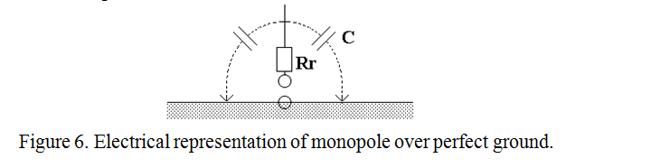
Current from the feeder completes its circuit through Rr, C and ground. In practice, the ground is not perfect but has resistance which raises the input resistance to the system and introduces loss. This loss can be ameliorated by using an “Earth Mat”. (As well as changes to the radiation pattern, the centre feed point impedance of both vertical and horizontal dipoles varies considerably with their height above ground).
The “Earth mat”
This usually takes the form of a set of radial wires laid just above or just below the surface of the ground around the monopole and connected to the co-ax braid. It should perform two main functions: a) provide a low resistance termination for the electric field lines, thus reducing loss, and b) reflect the whole of the image of the monopole in the ground. Ideally, it should extend to infinity, but in practice, from the efficiency point of view, it is satisfactory if it collects most of the electric field lines so that only a few weak more distant ones return their current through the lossy earth.
As far as reflecting the image is concerned, it should be large enough that the whole of the monopole is reflected in the ground mat at the elevation angle at which it is desired to propagate. (E.g. for reflection off the “F2” ionospheric region). The geometry can be imagined by a pencil, (representing the monopole), standing upright on its blunt end in the centre of a horizontal mirror. At high angles between the mirror and the eye of the observer, the whole of the inverted image of the pencil can be seen. However, the nearer the observer gets to the plane of the mirror, (the smaller the elevation angle), the larger the mirror needs to be to image the whole of the pencil. I.e. Low “take-off” angles need a large earth mat.
PRAECEPTOR
| Back |
|---|