| Back |
|---|
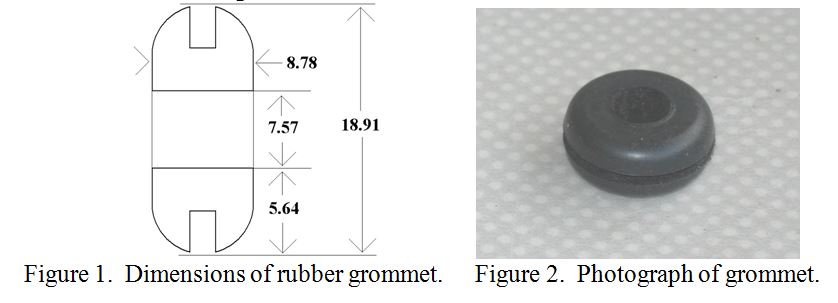
From these dimensions, the “core”, or winding area was calculated to be 49.53mm2 which is equivalent to a circular area with a diameter of 7.04mm. A wooden dowel was turned down to this diameter to act as a coil former, and drilled with two small holes to anchor a solenoid winding. This was to be used later for comparison of inductances.
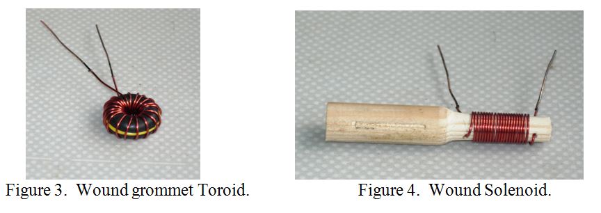
In order to prevent the winding compressing the slot in the grommet, (which normally engages with the hole in a chassis), two plastic sleeves stripped from PVC covered wire were pressed into it. The toroid was then wound with 0.68mm (bare), 0.73mm (enamel) wire, (thought to be 22SWG). 21 turns were required to completely fill the central region. A photograph of the completed toroid is shown in figure 3, which also clearly shows the yellow plastic sleeve filling the slot. Measurement of inductance was made using an “Atlas Peak LCR meter” at a frequency of 200kHz. This meter only reads to the nearest 0.1?H, but repeated measurements often yield readings differing by 0.1?H, which can be useful in indicating whether the actual inductance is slightly higher or lower than the figure indicated. The inductance of the “Ferriteless Toroid” was estimated at just over 0.3?H.
The wooden coil former for the solenoid comparison inductor was also wound with 21 turns as shown in figure 4.
One mechanical disadvantage of a solenoid compared to a toroid is the need to anchor the ends of the winding, otherwise, when the winding tension is released, the winding tends to unwind like a spring, resulting in slightly fewer turns of greater diameter. This tendency to unwind is much less prevalent with a toroid. By drilling holes through the centre of the wooden former and anchoring the wire ends through them, the wire at each end of the main coil represents half a turn, because it bisects the magnetic field emerging from the end of the solenoid. Thus the winding consisted of 20 complete turns plus two half turns. The inductance was again measured several times with the LCR meter and is estimated at just over 0.7?H, i.e. about twice that of the toroid.
In conclusion, it appears that winding an inductor as a toroid on non ferro-magnetic material is not an effective way of constructing an inductance compared to winding contiguous turns as a solenoid.
PRAECEPTOR
| Back |
|---|