| Back |
|---|
Part 1
Before describing the experiments which led to a useful device, let us first remind ourselves of a few things about dipoles. The half wave dipole, composed of metal rods or thickish wires, is probably the simplest and most energy efficient of all electromagnetic radiators. When fed at its centre, the feed point impedance is equal to the radiation resistance and is typically about 72 Ohms, although this depends slightly on the thickness of the dipole conductors. A single half wave dipole radiates equally in all directions normal to its axis, with radiation falling to zero off its ends, i.e. along its axis. Hence a vertical dipole is frequently used where “all round” communication is required and no communication is required vertically upwards. If a highly conducting “Earth Plane” is available, for example a car roof, a ship’s deck or an “Earth Mat”, then a quarter wave monopole suffices, as the lower half of the half wave dipole is effectively synthesised by the phase inverted image of the top half as seen in the ground plane. However, the use of a quarter wave monopole (fed at its bottom), and ground plane has the slight disadvantage that the radiation resistance and the feed point impedance, although still purely resistive are then only half that of a full half wave dipole. i.e., they are approximately 36 Ohms resistive, with the result that other resistive losses may become more important.
Sometimes, for reasons of space, wind loading, etc., a full half wave dipole or even a quarter wave monopole above a ground plane at the chosen wavelength may be inconveniently large and a shorter antenna has to be used. In which case a loading coil or “Antenna Tuning Unit” has to be used to obtain a reasonable match to the feeder and transmitter.
In my case, some years ago, I wanted to install a horizontal half wave dipole for the 6 metre band. I wanted it to be as high as I could reasonably get it in my loft roof-space, and I wanted to be able to turn it through 360 degrees. However, in the space available between the rafters, I couldn’t accommodate a full half wave length, (being about 3 metres long), so I decided to investigate shortened dipoles.
The two commonest means of reducing the physical length of such antennas, (while substantially preserving their radiation properties and the “resistiveness” of their feed point impedance), are capacitive and/or inductive loading. Capacitive loading is most effective when applied near the far ends of the antenna, i.e. near the high impedance, high Voltage ends of the antenna. Inductive loading is most effective when applied near the high current region, (i.e. at the centre of a dipole, or near the bottom of a quarter wave monopole over a ground plane). Typical examples of capacitive loading can be seen in “T” antennas on ships, or at Medium and Long Wave broadcast stations where the horizontal top wire, being fed at its centre, does not radiate appreciably but greatly enhances the vertically polarised radiation from the vertical wire connected to it. Typical examples of inductive loading can be seen as the little bulge near the base of car roof mounted “Whip” antennas on police cars and as the spiral spring at the bottom of some car mounted radio telephone whip antennas. Many hand held mobile phone antennas effectively combine both capacitive and inductive loading to reduce the physical length of their antennas by using a spiral or helical wire, usually inside a short plastic tube.
However, contraction of the antenna length from a half wavelength in free space, (or a quarter wavelength above a ground plane), causes a rapid reduction in the radiation resistance, causing the resistance of any inductance needed to tune it to contribute increasingly to the loss of signal, both transmitted and received. I reasoned that, if I could increase both the inductance and capacitance of my shortened dipole, and at the same time leave these parameters distributed along the dipole in roughly the same manner as in a full length dipole, the loss would be less than if I were to use lumped inductances and capacitances at specific points. I decided that the distributed inductance and capacitance would take the form of a well spaced out helix forming the arms of the dipole. I guessed that even if and when I found the resonant condition, the radiation resistance would be somewhat less than that of the normal dipole, (about 72 Ohms), and might be nearer 50 Ohms. Hopefully it would not be as low as that of a dipole shortened with the aid of lumped impedances. The antenna output connection on most modern transceivers is designed for a 50 Ohm load, so when it is connected to a half wave dipole, (of impedance 72 ohms), it produces a VSWR of about 1.5 which is normally acceptable. I hoped that my shortened dipole antenna might have a VSWR better than this.
I measured the roof space in which I wanted to fit the antenna and then found a well dried-out garden cane of the right length, (which had been used as a bean pole the previous summer), to use as a “former” on which to wind the rather well spaced out helix. There then followed a rather long series of experiments, (initially involving a dip meter, and, in the later stages, a 6 metre transmitter and a VSWR meter), in which the total wire length and number of equally spaced turns along the cane were varied, always keeping the length of the helix virtually equal to the length of the cane until resonance was achieved. A very rough indication of the appearance of the shortened dipole is shown in figure 1 below. (Note however that the length to thickness ratio of the cane and the number of turns are not accurately represented in the diagram).
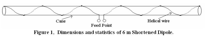
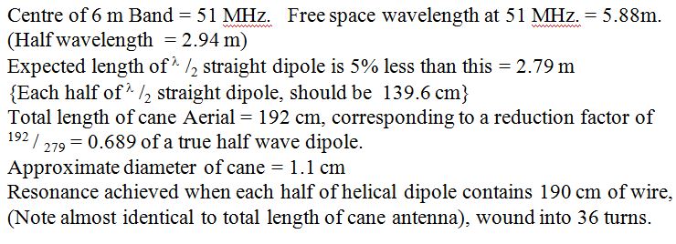
The successful dimensions and the relevant statistics were as follows:
The shortened dipole was fed at its centre with 50 Ohm coax via four small ferrite rings which just fitted over the coax and were pushed up close to the feed point. These acted as a “Choke Balun” to prevent any current from flowing down the outside of the outer of the coax to stop this from acting as part of the aerial. If this is not done, (with any aerial), the system behaves as two aerials connected in parallel where the feeder is connected. The two aerials are the wanted horizontal dipole and a vertical long wire, (the outside of the coax outer), tuned against the half of the wanted dipole which is connected to the coax centre conductor. Apart from radiating some vertical polarisation and distorting the wanted radiation pattern, the two aerials in parallel lower the feed point impedance.
The VSWR of the final aerial was a very satisfactory 1.08 at 51 MHz. (I did not investigate whether the dipole impedance was 8% higher or lower than 50Ω ?. In a normal half wave dipole, constructed of metal rods or reasonably thick wire, the resistance of the wire at RF is only a few hundredths of an Ohm compared to the radiation resistance of 72Ω, so virtually 100% of the power fed to it is radiated. The shortened dipole as described used multi-stranded tinned copper wire approximately 0.035 inch (0.889 mm) in diameter, and if it had been a straight half wavelength the calculated loss resistance would have been 0.29Ω. (See Radcom, May 2001, page 55). The meandering requires 36% more wire (increasing the loss resistance to 0.39Ω), and its radiation resistance has fallen to approximately 50Ω. On this basis it is probably over 99% efficient. The radiation pattern is expected to be substantially identical to that of a full half wave horizontal dipole.
Conclusion
Shortening the physical length of a dipole to 69% of its normal length by winding each arm into a widely spaced helix required more wire in each leg by a factor 190 / 139.6 = 1.36
The match of the shortened dipole to a 50Ω transceiver was considerably improved compared to a normal “full length” half wave dipole.
This has proved to be an extremely useful 6 metre antenna.
| Back |
|---|