AB INITIO
| Back |
|---|
This is a two part article about the polarisation of
Electro-Magnetic, (E-M), waves and how it affects their propagation. At
a fundamental level, the acceleration, (or deceleration), of electric
charge, (mainly electrons) always generates E-M radiation perpendicular
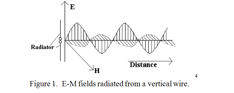
to the direction of acceleration. In a simple transmitting aerial, a
wire for example, where the electrons are confined to the direction of
the wire, the out going waves consist of an electric field parallel to
the wire and a magnetic field in phase with the electric field but
perpendicular to the wire, both propagating away from and mainly at
right angles to the wire At an instant in time, the electric field,
(E), and the magnetic field, (H), could be illustrated graphically as
shown in figure 1.
In radio science, (as opposed to optics), it is the electric field which defines the “plane of polarisation”. Thus the wave from a vertical aerial is said to be vertically polarised. In a Marconi style “inverted ‘L’ aerial”, the horizontal “Top” radiates horizontal polarisation and the vertical “up-lead” radiates vertical polarisation, and as they are in phase, the resultant is some sort of “slant” polarisation.
In the case of light or heat radiated from a flame or from the ionised gas in a neon or fluorescent tube, it is the millions of separate excited or ionised atoms which radiate as their electrons jump between orbits. As each atom has a different random orientation, so the radiation consists of millions of photons with millions of different planes of polarisation. The radiation is then said to be unpolarised. Pure polarised radiation can be obtained from this unpolarised radiation by means of a polarising filter such as is used in some sun glasses. This selects only those components of the randomly polarised input which are parallel to its reference plane, absorbing all the orthogonal components. i.e. such sunglasses incur a minimum of 3dB loss in brightness.
Practical aerials are seldom perfect, but a good “all metal” 2 metre or 70cm aerial can radiate about 99.9% of its energy with the desired polarisation, i.e. the “cross polarised” wave may be 30dB or more down on the wanted polarisation. There is not much point in aiming for near perfect purity of polarisation as by the time some of the wave has been scattered by nearby houses, or by the ‘E’ or ‘F’ layers of the ionosphere, its polarization is usually degraded and often completely scrambled. This means that it is often possible to get reasonable communication between stations with completely the “wrong” polarisation. There are however situations where choosing the correct polarisation is important, and this applies particularly to reflection of the wave from the intervening ground between the transmitter and the intended receiver.
Reference has been made several times in past articles to the fact that vertical polarisation is reflected off a horizontal conducting surface, (i.e. the ground) without a change of phase. Whereas, horizontal polarisation is reflected with a shift in phase of 1800. (These statements are only strictly true for conducting surfaces. With dielectric surfaces it is more complicated). Why should these things be so? The first part of this two part article attempts to explain from first principles how this occurs.
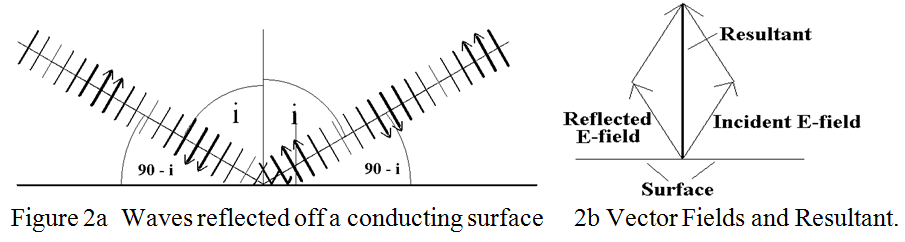
The difference in phase shift between the two polarisations occurs because of an absolutely essential property of electric fields. This may be stated as: “However it comes about, the resultant electric field adjacent to a conductor, always terminates on the conductor at right angles to it”. Thus any component of electric field adjacent to and parallel to the conductor is zero. The situation is depicted as a “sideways view” of a snapshot of the electric fields during the reflection process in figure 2a, where the wave is assumed to be travelling from left to right. But first, a word about the term “Electric Field Lines” which is used. These are imaginary lines of force showing the direction of the force which would act on an electric charge if it were placed at that point. An electric field line is sometimes drawn with an arrow head to indicate its direction, (i.e. positive to negative), with its length indicating its strength. The field line is then called a “vector”. However, this convention has not been used in figure 2a below. Here it is the “thickness” of the field lines which is intended to represent the amplitude of the beam impinging onto and reflected off of the horizontal surface. Note that, in the snapshot, the phase of the electric field reverses every half wavelength. Figure 2b shows that the resultant electric field vector, of the incident and reflected waves adjacent to the surface, is vertical. (The resultant is produced by completing the parallelogram of vectors in the usual manner of vector addition).
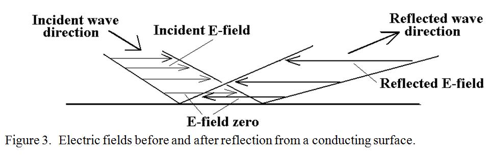
The situation for horizontal polarisation, (i.e. with electric field parallel to the reflecting surface), is shown in perspective view in figure 3. To understand this figure you have to imagine that you are standing to the South of a reflecting surface, watching the electric field lines coming in from the North West, being reflected and exiting over your right shoulder to the South East. As the moving electric field is reflected, it causes current to flow in the surface which tends to oppose the field which caused it, resulting in the reflected field being in the opposite direction to the incident field. The resultant field of the incoming and the outgoing horizontal fields adjacent to the surface is therefore zero which satisfies the essential condition stated above.
In a situation where both a direct ray from a transmitter and a ray reflected from the ground are received, constructive or destructive wave interference is determined by which polarisation is employed. For propagation near the ground, the direct ray and the reflected ray have similar path lengths, see figure 4.
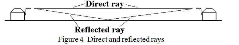
For near identical path lengths between the direct and the reflected ray, vertical polarisation will produce constructive interference, enhancing the received signal, whereas horizontal polarisation will produce destructive interference cancelling the received signal. This is an ideal case, nevertheless, it is the difference between the ways in which vertical and horizontal polarization are reflected from a horizontal surface, (i.e. the ground), which explains why a good signal is received by an aerial a few wavelength above the ground when vertical polarization is used whereas almost no signal may be received using horizontal polarization. However, small differences in effective path length, caused for example by local patches of warm or moist air, may temporarily negate complete nulling of signals and allow communication but with deep fading. Particularly with horizontal polarization, increasing the height of either the transmitting or receiving aerial increases the difference in length between the direct and the reflected rays, thus improving the received signal. This increase in signal strength with height is referred to as “Height gain”.
At long distances between the transmitter and receiver, (i.e.
exceeding several tens of miles), where there is little likelihood of a
“surface grazing” ground wave being received, horizontal polarization is
usually recommended as experience has shown that it has less tendency
to fading, although the reasons for this have not been firmly
established. However, the fact that it is so was born out,
(particularly at VHF), in a series of experiments carried out by the BBC
on the television bands IV and V in the 1960s.
Part 2 of this article will look at the attributes of circular polarisation.
| Back |
|---|
PRAECEPTOR