| Back |
|---|
My building and experimenting with a Tesla coil arose directly from my experiments with a spark transmitter, and this transmitter formed one of the essential units of my original Tesla coil system. But what is a Tesla coil system? It is a collection of fairly simple but basic units which together produce a very high voltage, high enough to produce a corona discharge into the surrounding air. It also produces this high voltage at a very low current and at a high frequency, such that the resulting sparks can be drawn off to one’s fingers. The current then flows to earth over the surface of one’s body without causing pain, damage or RF burns due to the “skin effect” of high frequencies.
The whole system actually comprises three stages or units; “the switch or pulse unit”, “the RF unit”, and the “Tesla Coil” itself, but the whole is colloquially just called “The Tesla Coil”. I shall describe each of these units and their operation in four separate short articles in the “Newsletter”. This first part describes the “overall system”, with subsequent parts dealing with the main units, and lastly some further experiments and measurements.
The first unit is what I call the “Switch Unit”. In early Marconi spark transmitters, this was the main and sometimes the only unit. It contained a “buzzer”, or electric bell mechanism for breaking up the direct current from a battery into short pulses of a few, or a few tens of milli-seconds duration, and this intermittent current was then passed through the primary of an induction coil. The output of this coil, at a few thousand volts, was applied across a spark gap, one side of which was connected to an aerial wire and the other side was connected to an earth wire, buried in damp soil. For ship borne applications, Marconi dispensed with the buzzer mechanism and used the ship’s mains alternator, (usually at 400Hz), and a step-up transformer to produce the sparks.
In my experiments on spark transmitters and Tesla coils I have tried both methods of producing high voltage sparks. (More on this latter). In both the Marconi style spark transmitters and the Tesla coil, the radio frequency power produced by the spark is prevented from being shunted by the self capacitance of the induction coil or transformer by a radio-frequency choke.
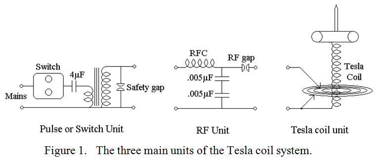
The Tesla coil itself is a loosely coupled tuned transformer, (both primary and secondary tuned to the same frequency, in my case about 2MHz), but with rather unusual inductance to capacity ratios. The primary, (with the RF spark gap short circuited), has a high Q and a high capacitance, (about 2.5nF, which is actually in the preceding unit which I call the RF unit), and low inductance, (3.7???. The secondary also has a high Q, but it has a very low capacitance, (a few pF), and a high inductance, (3.1mH). The basic circuit of the whole ensemble is shown in figure 1
In the second part of this 4 part article, I will describe the “pulse”, or “switch” unit. This uses a circuit not available to Marconi or Tesla as it contains the only semi-conductor device used.
| Back |
|---|
John, G0NVZ