| Back |
|---|
This article makes use of some of the reasoning and facts established in a previous article entitled “The Dipole”. However, these facts are fairly obvious and intuitive and are as follows:-
- 1) All wires carrying an RF current radiate (unless they are enclosed, e.g. by a coax shield), or are adjacent to another wire carrying an equal and opposite current, (e.g. a twin wire feeder).
- 2) The amplitude of the electric waves and the magnetic waves radiated by a wire are each proportional to the current in the wire.
- 3) The current in a wire can be increased many fold for the same available RF power by making the wire part of a resonant system.
Consider a wire with RF energy fed into its centre, (either by breaking it at its centre or by inductively coupling into it), such that it is symmetrical about its centre as shown in figure 1. Each arm has self inductance which increases as the arms are made longer and it has capacitance between the arms which also increases with their length. Although in reality these are both distributed along the arms, the centre fed wire aerial, (which we will still call a dipole although not a half wave dipole), can still be represented by the equivalent circuit as shown in figure 2.
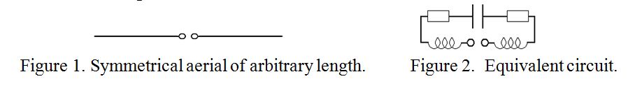
As explained in 3) above, for maximum radiation the wire should be made part of a resonant system and one way of doing this is by choosing the “right length”. The reason that there is a right length is because inductive reactance increases with increasing inductance, but capacitive reactance decreases with increasing capacitance. So, at any particular frequency, as a wire is lengthened there comes a point where the rising inductive reactance and the falling capacitive reactance become equal. Now inductive reactance is positive but capacitive reactance is negative, and they are effectively in series at the input of our short aerial, so their effective reactance becomes zero at this particular frequency. This is called the “resonant frequency”.
In addition to rising inductance and capacitance as the wire length is increased, there is also a small series resistance due to the radiation from the wire. This is shown by the rectangular boxes in the upper arms of figure 2. This “radiation resistance” is very small indeed for a wire length much shorter than a half wavelength, but it rises roughly as the square of the overall length to about 72Ω as the overall wire length reaches half a wavelength. A wire length equal to half a wavelength will not be considered further since no additional loading is required to bring the antenna system into resonance. The first overall length at which the inductance and capacitance become equal (and opposite in sign), is about 5% shorter than half a wavelength. Nevertheless, such an aerial is still called a “half wave dipole”.
A centre fed dipole shorter than half a wavelength is thus deficient in both inductance and capacitance for achieving self resonance. This can be remedied by adding additional “lumped” inductance or capacitance or both, or “distributed” inductance and capacitance in the form of additional line length to the non radiating parts of the system. The latter is probably the simplest to explain. Consider the aerial system shown in figure 3 in which the inner parts of the arms are brought together at right angles to the radiating part of the antenna.

This will still be self resonant if the total length of each arm is approximately one quarter wavelength long, although the feed point impedance will be rather less than 72Ω. This form of loading, (for aerials which would normally be too big for your garden), is exemplified by the “G5RV” and others. In principle, the parallel feeder portion could have any spacing and impedance, but as there will be standing waves on it, it is better to avoid low impedance coax which tends to be lossy at high VSWR.
A viable alternative is to introduce “lumped” inductance into the system as shown in figure 4 which makes use of the existing capacitance of the wire but adds inductance in series with it to achieve resonance.

Another alternative is to add lumped capacitance, usually applied to the ends of the dipole, which makes use of the existing inductance of the wires to achieve resonance as shown in figure 5.
All the systems discussed so far have been ideal “balanced systems”, clear of the ground. However, the principles are equally applicable to aerials tuned against ground, where, for “perfect ground”, (like a large copper plate or lots of radials), you only need, (in theory), half of any of the above systems, as indicated in figures 6 and 7. The ground, by the “mirror image effect”, provides the other half of the system.
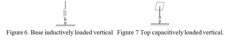
The plate at the top of the capacitively loaded antenna is sometimes known as a “capacitive hat”. In principle, loading may be applied to other parts of the antenna, and in particular, there is some merit in applying inductive loading part way up a vertical antenna, but discussion of this is beyond the scope of this simple explanation of “Loading”. When tuned against ground, a full quarter wavelength antenna is self resonant, and has an input impedance is about 36Ω, and rather less if it is shorter and loaded to achieve resonance.
PRAECEPTOR.
| Back |
|---|