AB INITIO
| Back |
|---|
As its name implies, a diode is any two electrode device used in electronics. When the word “diode” is unprefixed by any other adjective, it usually refers to a rectifier. There are two main categories of diode, Thermionic and Semi-conductor. This article deals only with the thermionic diode. A later article will deal with semiconductor diodes.
The very earliest diodes were thermionic and were produced by the electric light industry. They consisted of an incandescent filament and a metal plate, (these being the two electrodes), enclosed in an evacuated glass envelope and were usually used as a “detector” of radio signals or as AC mains rectifiers in “valve” receivers. They marked the introduction of “electronics” into the otherwise “all mechanical” science of wireless. Mechanical systems usually consisted of rotary spark or induction coil transmitters, (of Morse Code of course), and coherer or moving magnetic wire based receivers. As a detector, the thermionic diode acted as a rectifier of weak RF signals. As the transmitted signal consisted of an audio frequency train of RF pulses, the rectified received signal consisted of a train of unipolar or DC pulses which were audible in head-phones.
The mechanism of rectification in the thermionic diode is that as a DC current is passed through the thin filament, heating it to incandescence, some of the electrons comprising the filament current are given sufficient thermal energy to “boil off” into the surrounding vacuum of the lamp bulb. (“Heat” is after all, just the internal energy of motion of atoms and electrons. At a high enough temperature, electrons and eventually atoms reach their “escape velocity” and escape from their parent materials).
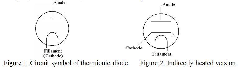
These escaped electrons form a cloud-like space charge around the filament. In the absence of the metal plate, they are collected up near the positive connection to the filament and were unnoticed by early lamp makers. However, if a metal plate is placed near the filament and connected through the glass envelope, a small current may be drawn from it and returned to the positive connection of the filament. A much greater current could be obtained from the plate, (now re-named the “Anode”), if it were made positive relative to the filament by a separate battery. However, no current would flow if the plate were made negative relative to the filament. I.e. current would only flow one way through the device, in other words it could be used as a “Rectifier” of alternating current and in particular of RF alternating current. The circuit symbol, (which is also a very good representation of how it works), is shown in figure 1. Indirectly heated versions, where the filament heated an electron emitting cathode, were also produced with a slightly modified circuit symbol as shown in figure 2.
Thermionic diodes were produced in various sizes. The tiniest diodes were formed by a metal strip a few mm long by about 2mm wide close to the existing hot cathode of an amplifying valve to perform the signal detection in a radio receiver, (the so called “diode or double diode triode”). There were bigger versions for the rectification of the mains for the High Tension supply of both small transmitters and radio receivers, supplying up to 250mA at 1000V. Two such diodes were frequently included in the same envelope for “full wave rectification”. The largest diodes made were huge 3-phase mercury arc rectifiers in glass spheres up to a metre in diameter as discussed below.
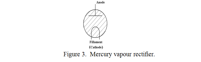
A derivative of the vacuum thermionic rectifier was the mercury vapour rectifier designed for higher current applications. This was similar to the vacuum version but was always directly heated and contained a few drops of liquid mercury which quickly became vaporised in use. The circuit symbol for a mercury vapour rectifier is shown in figure 3.
The action is that initially, it behaves like the vacuum version but the electrons streaming from the cathode, (filament), to the anode ionise the mercury vapour. This releases more electrons and an avalanche process ensues greatly reducing the internal resistance of the device. Whereas in a power rectification circuit the voltage drop across a vacuum rectifier is in the order of 100V at full current, that across a mercury vapour rectifier is about 15V. These devices were fussy however. The filament had to be allowed to reach its full operating temperature before the voltage to be rectified was applied for fear of damaging the high emission coating on the filament, and they were limited to about 1000V “peak inverse voltage” for similar reasons due to the bombardment of the filament by the heavy mercury positive ions.
The largest mercury vapour rectifiers, (called mercury arc rectifiers), were used for rectifying the AC National Grid supply at around 600V three-phase at 1000A for London Tube trains and the “Southern Railway”. These last were eventually developed into the so called “pumpless steel tank” rectifiers. Both the glass and steel tank versions relied on a pool of hot liquid mercury as the cathode, and ionised mercury vapour for conduction from the cathode to each of several anodes.
These have all been superseded now by various types of semi-conductor rectifier, which will be the subject of a future article.
PRAECEPTORThe Thermionic Diode (continued)
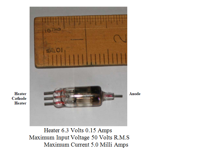
After this discourse on the thermionic diode by Praeceptor I thought that I would add a photograph of the smallest indirectly heated, stand alone, one (i.e. excluding the double diode triode mentioned earlier) that I possess.
I used this in a television that I built in 1949 as a video signal detector and another as a D.C. restoration component in the Cathode Ray Tube drive circuit.
Dennis G8VRO
| Back |
|---|