The Switch Unit
Back
In part 1 of this four part article I described the overall system and its purpose. In this part I shall describe what I call the “Switch Unit”, or “Pulse Unit”, which is the means of generating pulses of a few thousand Volts about one hundred times per second. In the “spark transmitters” of the early 1900s, Marconi used either a battery powered buzzer or electric bell type mechanism, or, when on board ship, the ship’s alternator to supply the interrupted current to the primary of an induction coil. I experimented with both a buzzer and a 50Hz mains powered system and eventually decided to use the “mains powered” system in the switch unit as it generated about twice the RF power of the buzzer system.
The Switch Unit
This made use of a readily available light dimmer switch in a slightly novel way to supply current pulses to the primary winding of a step-up transformer. The step-up transformer used a car ignition coil as this was easily available and could handle the high voltage, (over 10kV), of its output. However, the ignition coil was found to be very inefficient with such a low frequency input of 50Hz sine wave, and required some form of “interrupter” to start and stop the current more quickly than occurs with a sine wave. Instead of using an electro-mechanical system, (as in a buzzer or electric bell), I experimented with a solid state triac system as used in a light dimmer switch. This works by switching the mains voltage to the load at a variable point during each mains half cycle, depending on the position of the control knob. Switching off occurs automatically twice per cycle at the voltage cross-over point between positive and negative half cycles. I reckoned I would need to switch the mains across the primary of the ignition coil, (but only for a milli-second), at the peak of each half cycle for maximum effect. The duration of the “on” period is effectively controlled by the time constant of a 4µF capacitor in series with the primary resistance and inductance of the car ignition coil.
However, mains dimmer switches are designed to work with a resistive load, and the variable turn-on point is obtained by turning the control knob which varies the resistor of an R-C phase shifter. In my case the load was essentially capacitive, so I didn’t expect the control knob to work in the same way. I found that, instead of the switch-on point for maximum sparks being at approximately the half way point of the knob’s rotation, (i.e. at the peak of the AC waveform), it was actually at near the minimum or dimmest point. I have to admit that I blew up the first dimmer switch within a few minutes of otherwise satisfactory operation. I calculated that the dimmer switch was handling peaks of about 20 Amps, (it is probably designed for a load of a couple of hundred watts, say 1 Amp maximum). I therefore experimented with different size capacitances in series with the primary of the ignition coil to reduce the energy in the pulses, and eventually settled on 4µF. I also purchased a “double dimmer unit”, and fitted a separate switch so that I could easily switch to the second dimmer if the first failed during experimenting or demonstration. The current unit has not failed and has performed satisfactorily for several hours and for several demonstrations over the last 10 years, although I tend to only run it for about a minute at a time. The “Switch Unit” comprising dimmer, capacitor, step-up ignition coil transformer and “Safety spark gap” is shown in the photo of figure 2.
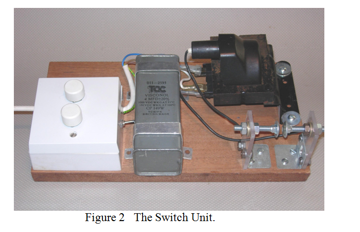
The “safety spark gap” on the switch unit, (seen in the right hand bottom corner of the picture), hopefully never comes into use. It is designed to prevent the step-up transformer ever seeing an open circuit which may lead to internal sparking and its destruction. It is set to spark over at about 5kV. It also provides one with a sharp reminder that the mains is “On” when it is not connected to the following unit, the RF unit. When properly connected to the RF unit, that unit’s own spark gap breaks down at slightly less than 5kV to generate RF pulses. In part 3, I will describe the “RF Unit” and the “Tesla Coil Unit”.
| Back |
|---|
John, G0NVZ