| Back |
|---|
What’s in a Word?
First of all what does the word “Dipole” mean? The Chambers dictionary definition of dipole is: “having two poles: two equal and opposite electric charges or magnetic poles of opposite sign set some distance apart: a body or system containing either of these”.
Examples include a bar magnet, or in chemistry, a molecule in which the electron orbits result in a positive electric charge at one end of the molecule and a negative charge at the other. However, these are “static” dipoles. We are mainly interested in “dynamic” dipoles in which the sign of the two poles alternate.
In the context of radio communication, “dipole” usually refers to a simple antenna, usually centre fed. When unprefixed by any other adjective, “dipole” usually implies a “half wave dipole”. In older amateur radio literature it is sometimes referred to as a “doublet”, but for our purposes the two terms are synonymous. There are actually four distinct types of dipole antenna: Magnetic, Short, Electric, and Half Wave. Only the half wave dipole will be considered in detail. The dipole is an “Antenna”, which means it is a transducer between the voltage and current supported by the “go and return wires” of a feeder, and the mutually self supporting electro-magnetic waves radiating from it into space.
Electro-Magnetic Waves.
E-M waves were predicted by James Clerk Maxwell in the 1840s and embodied in his famous equations. The waves and the voracity of his equations were subsequently confirmed experimentally by Hertz.
Since this is an Ab Initio article, it is hoped to make the explanation of the working of a dipole antenna intuitive and non-mathematical. However, certain statements derived from Maxwell’s equations must then be accepted as dogma as their derivation from first principles is complicated and requires considerable previous knowledge. These statements are basically:
1) A difference of potential, (measured in Volts), between two places gives rise to an electric field between these places. The direction of the field is from the higher, (positive) potential to the lower. If there are charge carriers, (e.g. electrons or ions), in this field, positive charge carriers will flow in the direction of the field and vice-versa. (i.e. a current will flow).
2) An electric current always surrounds itself with a magnetic field, (whose direction is given by “Maxwell’s cork screw rule”).
3) A changing magnetic field gives rise to an electric field at right angles to it whose strength is proportional to the rate of change of the magnetic field.
4) A changing electric field gives rise to a magnetic field at right angles to it whose strength is proportional to the rate of change of the electric field. This occurs even in the absence of charge carriers.
These statements describe a wave in which the electric field, E, supports a perpendicular magnetic field, H, and the magnetic field supports a perpendicular electric field, both being perpendicular to the direction of propagation of the wave. This wave is self supporting and requires no “medium” to travel in. The undulating electric and magnetic fields are in-phase having their maxima and minima coincident in time and distance and posses “power equal to the product of the magnitudes of the two”. Their “sense” is indicated in the figure 1. The two fields travel together in a constant ratio which depends on the medium in which they travel. The ratio of electric to magnetic field has the dimensions of Ohms, (resistive) per square, and in free space, (in vacuo), the ratio is equal to 377Ω. (“Per aquare” has no dimentions).
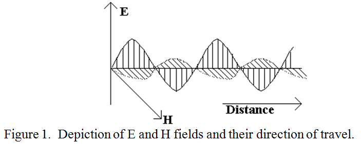
(Please note that I believe this is drawn incorrectly in some editions of the RSGB Radio Communications Handbook).
Launching the wave, the Transducer.
Consider a vertical conductor as shown in figure 2, and consider a current flowing from the positive end to the negative end. The resulting magnetic field, H, is as shown.
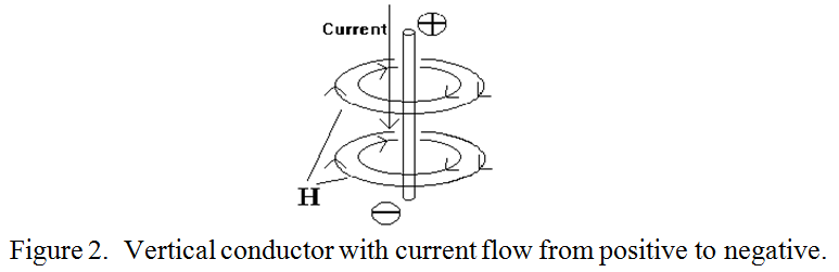
(In actuality, the charge carriers in a conductor are electrons which are negative and they flow from negative to positive but the result of the two negatives cancel out and so they do not affect the argument). The magnetic field lines may be imagined to spring out from the wire when the current is turned on and to collapse inward when it is turned off. However, most of the energy of the magnetic field is not radiated but is returned to the wire on switch off in the form of a voltage spike in the wire. I.e. this is “stored energy” as explained later.
In a neutral conductor there are as many electrons as there are positive protons in the nuclei. If, by some means, electrons are induced towards the top end of the vertical conductor, that end will be negatively charged and the other end, (now deficient of electrons), will be positively charged. Like charges repel each other strongly causing a pressure, (voltage), so that if the “inducement” is removed, the electrons at the negative end will surge away from each other towards the positive end. Rather like a swinging pendulum, they will over-shoot the equilibrium condition and the situation will be reversed with the top end now positively charged. In the absence of damping this oscillatory condition will continue ad infinitum. When the electrons are mainly at one end, they distribute themselves roughly as a “cosine shaped” distribution, as indicated in figure 3a. As they repel each other and move, the number flowing in different parts of the rod is roughly as indicated by the “half sine wave” shape shown in figure 3b.
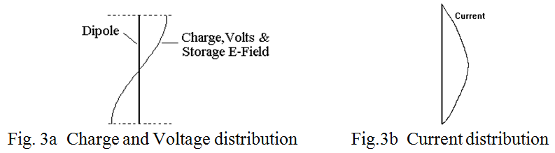
Now electric charge carries with it electric field emanating from it, and the flow of charge constitutes an electric current which surrounds itself with a magnetic field. So we appear to have all the necessary ingredients of a transducer for turning charge and movement of charge into electromagnetic waves. In fact these pictures are often reproduced in amateur radio text books but they are not the electric and magnetic fields responsible for radiation because they do not exist at the same time. The figure 3a distribution of voltage and electric field has its maximum when the current and hence the magnetic field is zero and the figure 3b distribution of current has its maximum when the electric field is zero.
In other words, these E and H fields are in phase quadrature in time, and so do not represent a flow of power although each contains energy which is exchanged between one and the other. These fields can be detected at close range by probes or loops, but they are components of the “Induction Field”, (sometimes known as the “Storage Field”), the strength of which is actually many times the eventual radiated field. What happens is the surrounding space, (by virtue of its 377Ω resistance), exerts what could be described as a small “viscous drag” on the E field relative to the H field, so the two fields are no longer exactly in phase quadrature. (They only differ by a few degrees of phase).
The resulting E and H fields, with a small phase shift between them, may be resolved into two new E and H fields, one, the induction field, where the E and H components are truly in phase quadrature and do not radiate, and the other, much smaller component, in which the E and H fields are in phase and do radiate. The much larger induction field falls off fairly rapidly with increasing distance from the antenna and becomes equal to the radiating field at a distance of λ/2π, (about 1/6th of a wavelength). Beyond one or two wavelengths the induction fields have fallen to a negligible level, whereas the radiating fields expand outwards falling off linearly with increasing distance.
Just as in the case of quarter wave transformers in transmission lines theory, where zero impedance, (short circuit), at one end can be transformed into infinite impedance, (open circuit), at the other, so the quarter wave arms of a half wave dipole transform the ratio of voltage and current along the arms of the dipole from low impedance near its centre to high impedance near its ends. When coupled to free space, (of impedance 377Ω), a break in the centre of the dipole, (where you would connect the feeder), shows an impedance of about 72Ω (depending to a small extent on the conductor thickness and proximity effects), and an end impedance of many thousands of ohms.
One way of looking at the “Q” of any component is as the ratio of the storage field to what may be described as the “working field”, and in the simple dipole this is about 10. If the aerial were another sort of transducer, (for example an electric motor), and not a radiator, it would be considered to have a rather poor power factor. However, the strorage fields inherent in resonance ensure that energy not radiated on the first pass of the current is radiated subsequently.
Where does the wave come from and where does it go?
Fundamently, the radiated wave comes from the acceleration (or deceleration) of charge, and therefore the whole length of the dipole does not radiate equally strongly. Because the alternating current in the wire varies along the length of the wire with a half sine wave distribution, so also does the magnetic field, and so also does the radiated electric field which is the result of the changing magnetic field. Each of the radiated fields thus has the same distribution as the current. I.e. most of the radiation comes from near the centre of the dipole.
The E-M wave generated by the alternating current in the wire expands outwards from the wire, carrying energy equal to the mathematical product of the strength of the radiated E and H fields. However, each radiated field decays inversely with the distance from the wire so that their product decays inversely as the square of the distance from the wire. The radiation field which surrounds the wire is not uniformly strong in all directions. It is strongest in directions at right angles to the current flow in the wire and fall in intensity to zero on the axis of the wire. I.e. the wire exhibits directivity in its radiation pattern, the energy being concentrated in some directions at the expense of others. The power measured in the direction of maximum power, (in the plane at right angles to the axis of the wire), divided by the power which would have been received at the same distance if the power had been spread uniformly in all directions, (as from an “isotropic radiator”), is known as the “Gain” of the dipole over an isotropic radiator. It is about 1.6 times or 2.15dB.
| Back |
|---|