| Back |
|---|
Introduction
Many radio amateurs have difficulty understanding the mechanism of “aerial gain”. But first, what is meant by the “Gain of an Aerial”? For a transmitting aerial it is its ability to concentrate the radiated power in a given direction so as to increase the signal strength at a receiver in that direction. For a receiving aerial it is the ability to capture more signal from a given direction than a simple aerial such as a dipole or a theoretical “isotropic radiator”, (i.e. an aerial which would radiate equally in all directions). In both cases the gain, (measured as a factor or in dBs), is always referenced to a dipole or to a theoretical isotropic aerial. (You cannot actually make an isotropic aerial but it is a useful concept). An aerial is both passive and reciprocal and its gain is the same on both transmission and reception. Gain is sometimes referred to as “Directivity”, but for the purposes of this article the terms are synonymous. “Gain” when applied to an aerial does not mean it actually amplifies like a transistor, but it behaves as if it were somewhat bigger. It is the purpose of this note to explain how it accomplishes this.
In order to understand the reasoning, it is necessary to accept a couple of essentials. Firstly, that radiated electric and magnetic fields can pass through each other without disturbing each other. Secondly, that the resultant field at any point is the sum or their constituents, taking into account the relative phases of the constituents.
Radiation
Consider a plan view of the radiation from a single radiator, for example a vertical dipole. It radiates in all horizontal directions, (i.e. in the plane of the plan), equally. If, (at any instant of time as the waves spread out), successive positive peaks of the electric field are joined by “contour lines”, then a “snap-shot” representation of the dipole and its radiated waves would appear as in figure 1, where the spot marked “A” is the position of the dipole seen end-on from above. .
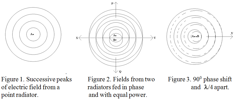
If now a second radiator, designated “B” is placed a short distance from A, and fed with an equal RF power in the same phase, (and provided the field from B does not affect the radiation from A and vice-versa), the combined fields will appear as in figure 2.
It can be seen that the only directions in which the fields add constructively are those marked “X” and “Y”. (Putting a metal screen a quarter of a wavelength to the left (say) of the dipoles will eliminate radiation in the “X” direction and give a single beam in direction “Y”). Very little radiation will occur in directions “P” and “Q” because the positive peaks from one aerial will fall near the negative peaks from the other. This principle may be applied to any number of equally fed radiators, and the result is known as a “broadside array”.
Gain on transmission.
Consider that, when RF power is fed to a single radiator, (A), the power received at a distant point is measured and used as a reference. Now consider that the same amount of power is fed to two radiators, (A and B above), so that the power radiated by each is 3dB down on that originally supplied to the single radiator. The electric field radiated by each will be 1/√2 times or 0.707 of the reference case because power is proportional to the square of the electric field.
However, the field received at some distant point where the fields add constructively will be the sum of the fields from radiators A and B which will be 2×1/√2 times the reference case. Hence the power received from the “two radiator array” will be (2/√2)2 = 2 times the reference case. I.e. the “two radiator array” has twice the gain or +3dB over that of the single dipole. Where has the increased received power come from? It has come from the decreased power in directions “P” and “Q”. If the radiators are spaced half a wavelength apart, the power radiated in directions P and Q will be exactly zero and the radiation pattern will be the familiar “figure eight on its side”. The principle may be applied to any number of radiators with gain over a single radiator being proportional to the number of radiators. To get the shape of the radiation pattern you will need some trigonometry, which is beyond the scope of this Ab Initio article.
Now consider the case where two radiators a quarter of a wavelength apart are fed with RF power with a 90 degree phase difference. The resultant fields are shown in figure 3. It is seen that the fields only add constructively in the direction “Y” and that the positive field peaks fall on top of the negative peaks in the reverse direction, thus cancelling the field in that direction without the need for a reflector. An array of radiators in line with the main direction of propagation is known as an “End Fire Array”. Except for a small number of radiators, the gain of this type of array cannot be calculated as above and it is not proportional to the number of radiators as there is strong interaction between the field due to some radiators and the radiation from other radiators as the beam is concentrated around them. However, in this case the strong interactions may be taken advantage of and only one radiator need be driven, but the lengths and spacing of the non-driven or “parasitic” radiators is then critical if each is to re-radiate in the correct phase and make its maximum contribution to the outgoing beam. This is the basis of the Yagi Array.
Gain on reception.
It often happens in science that different aspects of the same phenomenon are best explained by different models and this is the case with antennas. Whereas it is easy to imagine a number of separate radiators each producing separate fields at a distant point which add, thus giving “gain” to the received signal, it is less easy to envisage a passing wave being “sucked in” to a receiving antenna. The statement that “passive devices are reciprocal”, although correct, seems an unsatisfactory explanation, and many have a reluctance to accept it. Hence different models will be used to explain transmission and reception. To explain “Gain on reception” I will use the concept of a “Slow Wave Structure”.
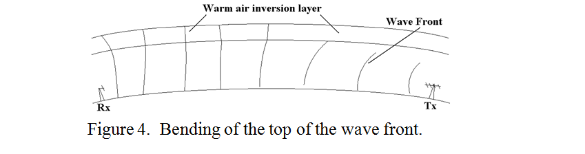
Forget “Plan Views” of wave peaks and consider a “sideways view of the wave fronts”. It is well known that a weather “inversion layer” gives extended propagation on the VHF and UHF bands. This is because the upper region of the wave fronts get into the warm, lower refractive index air of the inversion layer and therefore travel faster than the parts of the wave front lower down in denser air. This causes a bending forward and downward of the wave that would otherwise be lost into space. The situation is indicated in figure 4. A similar mechanism also accounts for the bending back to earth of HF waves by the ionosphere.
Exactly the same thing happens if the bottom of the wave front is slowed down by some means. Such means can be the surface of the earth although the “earth loss” tends to outweigh the curvature effect. The sea has however been used to good effect in “Over The Horizon Radar” systems which have tracked low flying planes and ships to a range of hundreds of miles. Artificial slow wave structures consisting of linked rings, metal corrugations or a metal spiral are used in travelling wave tube amplifiers and particle accelerators to match the speed of the wave to that of electrons in the electron beam, which then ride the wave rather like a surfboard rides a sea wave.
The succession of “directors” of a Yagi array behaves in a similar manner which slows the part of the wave nearest to the array compared to that farther away and this is what focuses or “sucks in” a wave that would otherwise have passed it by. An impression of the wave fronts as they enters a Yagi array is shown in figure 5.
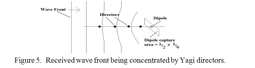
It is seen that the wave front bends inwards so that a wider area of the approaching plane wave is forced through the relatively small capture cross section of the dipole which is a mere one eighth of a square wavelength. (Imagine the dipole capture cross section as the full width of the dipole times the length of one arm). Actually, the “slow wave structure” explanation also works, though perhaps less convincingly, for transmission.
| Back |
|---|