It would be no good removing the man-hole cover in the pavement and directly measuring the resistance between the metal pipes at either end of the plastic section, as these would be effectively shorted out by the surrounding earth, so I decided to simulate the real situation by measuring the resistance of a length of similar plastic pipe filled with tap water.
I had no access to the type of plastic pipe actually used by the Water Board, although I had had a good look at it during the hole digging operations in the street, and down my own man-hole. The pipe was blue, about two inches in external diameter with quite thick walls to withstand the mains pressure. The nearest I could obtain was 1¼ inch plastic waste pipe. This was quite thin walled, (about 2 mm), but probably had a similar internal diameter, (measured at 31.5 mm). A roughly 2½ foot length was selected and a water-tight bung was made for one end. On the inside of the bung I placed a 31 mm diameter aluminium disc secured by a 6 BA screw which passed through the bung to a nut, thus making the bottom connection to the water. A similar aluminium disc with wire attached was fixed to the end of a 3 foot length of ? inch wooden dowel to be inserted into the top of the vertical plastic pipe. The dowel was marked off in 10 cm intervals. An impression of the apparatus is shown in figure 1.
The pipe was ¾ filled with tap water and a preliminary measurement of resistance was made with a multi-meter to get some idea of the order of magnitude involved. The resistance of the water column appeared to be thousands to tens of thousands of ohms, depending on the length of dowel inserted, so it was obvious that the 12-0-12 volt transformer which I had used for making earth rod measurements would be inadequate as the most sensitive AC range on my multi-meter was 0 to 100 mA. A transformer with 50, 100, and 250 volt tapings was therefore selected. 50 volts proved barely adequate for accurate measurement of current. The output voltage of the transformer was measured accurately as was the current for various separations of the aluminium electrodes and therefore the effective length of the water column.
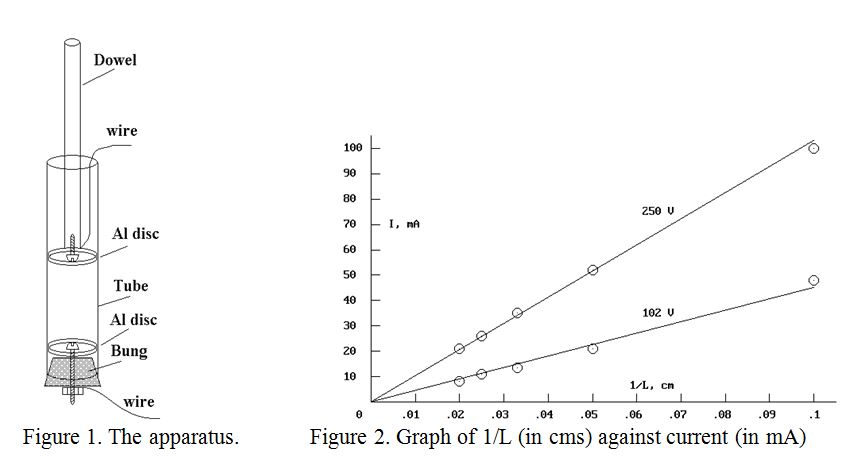
If the resistance of the water column were proportional to its length, (as expected), then a plot of current against the reciprocal of the length of the water column should yield a straight line. The plots of current against reciprocal of length for 102 volts and 250 volts are shown in figure 2 above. Fairly good straight lines are observed.
Converting between milliamps and amps, and centimetres and metres, and juggling with the variables gives:
resistance (in ohms), per metre length of water column = Volts/Slope of line
The 250 volt line on the graph, (believed to be slightly the more accurate), had a slope of 0.0103 Amp.metre, giving a resistance of 24,272 Ohm per metre, and the 102 volt line had a slope of 0.0045 Amp.metre, giving a resistance of 22,667 Ohm per metre in the 31.5mm internal diameter pipe. The former value of resistance gives a Specific Resistivity for the local water company’s tap water in the St. Albans area of 18.7 Ohm.metre
The conclusion is that the conductivity of the water in the metre length of plastic pipe between the domestic side of the supply and the iron street main does virtually nothing to improve the effectiveness of one’s “water main earth”.
Caution. Although it would be interesting to have the above results confirmed by other observers, it should be noted that the use of a couple of hundred volts between electrodes in a wet environment, which is likely to be an earthed stainless steel kitchen sink, needs caution, even when using an isolation transformer. Wellington boots and one hand in the pocket is usually a good maxim when the mains power is on.
John, G0NVZ