The Problem
Most general coverage receivers have adequate gain and you can hear the background atmospheric noise from the receiver’s bottom frequency limit of around 30 to 100 kHz up to their maximum frequency of 30 MHz: that is except for the “Medium Wave” range of 500 kHz to 1.620 MHz. The reason that most receivers are so poor at Medium Frequencies is that they automatically switch in a fierce attenuator when the medium wave band is selected. They do this because most medium wave broadcast stations are about 40 dB stronger than all other stations and most receivers can’t handle such huge signals without causing intermodulation products which would otherwise spill over into the adjacent bands. My general coverage receiver is the TS850 transceiver, but it is typical of its type. I could hear the background atmospheric noise at 499.99 kHz but it completely disappeared when going up another 10 Hz or into the 501 to 504 kHz band.
A Solution
The first stage was to locate and bypass the automatically switched attenuator, but that is another story. Having done this, the atmospheric noise was clearly audible but so were all the medium wave stations’ intermodulation products. What I then needed was a filter which passed frequencies of 501 to 504 kHz with not too much attenuation, but severely attenuated, (by at least 40 dB), all the medium wave stations. I decided that a simple series resonant circuit, consisting of a single inductor and a variable capacitor, would be adequate. The “trick”, so to speak would be to obtain sufficiently high “out of pass-band” attenuation while keeping the “pass band” attenuation reasonably low and this would require some optimisation. I decided that the inductance would need to be high and the capacitance low. As the filter would be placed in the 50 Ohm coax feeding the aerial, I reckoned that inductive and capacitive reactances of about 100 times 50 Ohms would be required. (This does not imply a Q of 100. The 50 Ohms at each end of the filter are effectively in series and also there is bound to be some loss in the inductor. In any case, the receiver input impedance and certainly the aerial impedance are probably not 50 Ohms).
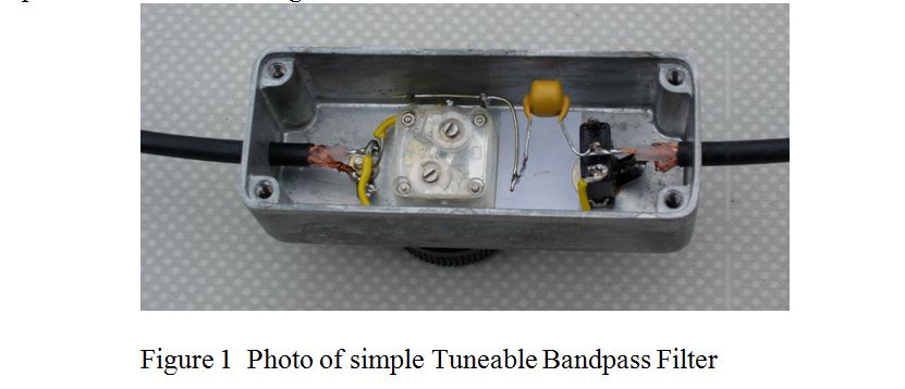
The design eventually used was an inductance of 2.2 mH in series with a 20 to 250 pF variable capacitor salvaged from an old transistor radio, the pair being capable of being bypassed by a small switch to give a “through” position. All were enclosed in a die-cast box with flying leads terminated in a PL259/SO239 plug and socket. The complete unit is shown in Figure 1.
Performance
As it was designed as an “in line” unit for 50 Ohm coaxial aerial feeder, it was first placed between a 50 Ohm pad from a signal generator and a 50 Ohm “through load” to an oscilloscope, and its throughput was measured with changing frequency. The 3 dB bandwidth was 11 kHz and the loss was 7 dB, at 502 kHz, roughly what was expected. However, when placed between the TS850 and 60 yards of RG213 coax ending in a 50 yard aerial wire, (the way it was intended to be used), its loss was only 3.5 dB, which was even more satisfactory. Also, the sharp increase in atmospheric noise as the unit was tuned through the receiver frequency was very marked, which made it easy to tune.
When the unit was used directly between the transceiver and a 50 yard wire aerial with no coax between them, it acted as an ATU, tuning out the reactive part of the aerial, and signals and noise were some 15 dB greater than when using the coax fed aerial wire. Suppression of strong Medium Wave broadcast stations above 909 kHz, (Radio 5), was at least 60 dB with no trace of intermodulation products with the filter “in”. In summary; this is a useful piece of kit for the MF station logger, very simple to construct, that works as expected.
John, G0NVZ