| Back |
|---|
Operation
The two 0.005µF capacitors in series, (shown in figure 1 of part 1), charge up via the Tesla primary to 5kV during the pulse of “stepped up” mains supply every 10ms. When the voltage across the capacitor reaches about 5kV the RF unit’s spark gap breaks down and the charged capacitor is effectively placed across the Tesla coil’s pan wound primary winding. A large current, (10s of amps), flows from one terminal of the capacitor to the other via the Tesla coil’s primary winding. As is usually the case when a capacitor dicharges into an inductor, the current rush “over dose it” as a result of the reluctance of the inductance to let the current fall once it has started, with the result that the capacitor is again charged to nearly its original potential, (5kV), but in the reverse polarity. The loss occurs mainly in the resistance of the spark. The whole process is repeated over and over again in the usual manner of resonant circuits, until there is insufficient voltage to maintain the spark. (In practice, about 10 cycles of exponentially decaying voltage occur). A similar but much larger voltage waveform is induced in the tuned secondary winding due to its much larger number of turns, resulting in a corona discharge into the air of about 150kV. The whole process is repeated 100 times per second.
Some further experiments
At the beginning of my experiments with a Tesla Coil, I used a Marconi style untuned spark transmitter as the “switch unit” or “pulse” unit. I knew that this produced “radar like pulses” of very short duration with a relatively long interval between them, (a duty ratio of several 1000 to 1). Although I guessed the peak power was high, I suspected that the mean power was very low. I attempted to measure this with an artificial load as shown in figure 6.
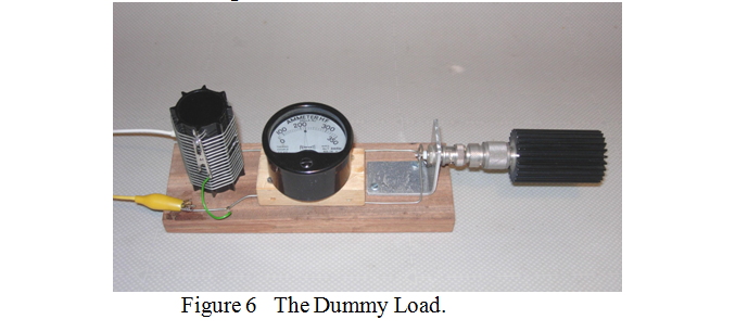
The Tesla primary winding was replaced by a similar value inductor across which was connected an RF ammeter in series with a 50? load. Although I don’t suppose this dummy load system was very well matched to the spark source, it would at least give an indication of the mean RF power produced using the usual P = I2.R formula. The best reading I got was 410mA, corresponding to a mean RF power of 8 Watts. (This was about twice the power obtainable from the battery operated buzzer type Marconi style transmitter). Unfortunately, at this point I overloaded and blew my thermo-couple RF ammeter so subsequent measurements had to be made using a “brightness calibrated” cycle lamb bulb, (several of which I also blew during experiments).
As a further, non-quantitative check on the RF power being produced, the 50Ω load was disconnected and a simple “loop lamp” using a 3.5 volt torch bulb was held near the coil. It could be made to glow brightly, as shown in figure 7.
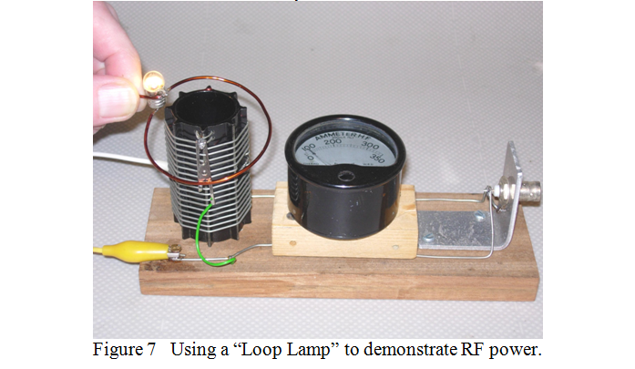
(Using a loop-lamb coupled to an inductor across the output of a transmitter provides an interesting demonstration, but it is not a trick I would recommend repeating using a modern solid state transceiver, as, until the loop lamp is drawing power, the coil presents virtually a short circuit to the transceiver which may damage it).
I must confess that I was surprised at the mean power being generated, (8 Watts), from relatively “intermittant” sparks. I therefore decided to investigate the efficiency of the spark transmitter as an RF generator. With an AC current meter in series with the mains supply and dimmer switch, the system took 140mA, which at 230 Volts represents a power of 32.2 Watts. The “wall socket” efficiency is therefore 8/32.2 = 24.8%. As far as conversion efficiency of “raw mains” to RF is concerned, it would appear that Marconi’s broad band spark transmitters were almost in the same league as modern transceivers!
That concludes my description of, and the fun I have had with, a home made Tesla coil and part of a replica Marconi spark transmitter.
| Back |
|---|
John, G0NVZ