AB INITIO (Capacitors at AC)
| Back |
|---|
In a previous article, I described how a capacitor could store and subsequently release electrical charge, and that the voltage across its terminals was proportional to the charge stored. I used the analogy of water in a straight sided tank where the height of water and therefore the pressure at the bottom of the tank was equivalent to voltage, the cross sectional area of the tank was equivalent to capacitance, and the flow of water into or out of a pipe at the bottom of the tank was equivalent to current. These were analogies for the capacitor under static conditions, i.e. at DC. In this article, I will describe what happens when the current is changing as in alternating current, (AC).
When a capacitor is first connected across a battery, there is a large inrush current as the capacitor is charged up to the voltage of the battery. This is frequently accompanied by a spark. If the capacitor is then disconnected from the battery and its terminals short circuited, the capacitor discharges in a large “outrush” current, also frequently accompanied by a spark. In these cases the size of the inrush or outrush current and how long it lasts depends on any resistance in the circuit, either in the battery or in the capacitor. It is more instructive to place a known resistor in circuit and measure what happens. Consider the simple circuit shown in figure 1.
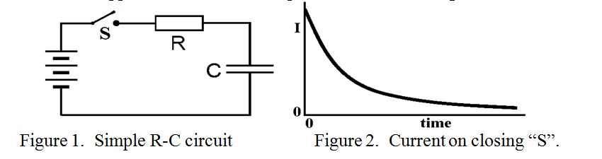
On closing the switch “S”, the inrush current is limited by the series resistor, “R”. but as the capacitor charges up towards the battery voltage, the difference between the capacitor voltage and the battery voltage, (i.e. the voltage across R), falls, and so does the current, I, as shown in figure 2. The voltage across the capacitor terminals gradually rises until it eventually equals the battery voltage as indicated in figure 3.
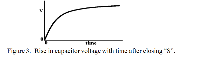
It is noticed that immediately after “switch-on”, although the voltage across the capacitor is low, its “rate of rise” is at its highest when current is at its highest. In turn, when the voltage across the capacitor is at its highest the rate of change in current is at its lowest. This is one of the fundamental properties of circuits containing reactive, (i.e. capacitive or inductive components). Unlike Ohm’s Law and resistors, where the voltage across the component is proportional to the current, with capacitors it is the rate of change of voltage across the component which is proportional to the current. (Incidentally, in a similar situation of an inductor in series with a resistor, the voltage across the inductor is proportional to the rate of change of current). So what happens to the current into and out of a capacitor when the voltage is changing constantly, both up and down as in alternating current? The same rule applies. Now the only AC waveform which we will consider in the sine waveform. (All other waveforms can be synthesised from a combination of sine waves of different frequency and phase). A sine wave goes from zero up to its positive maximum and down to zero followed by a negative excursion to its negative maximum and back to zero in a smooth manner. This process is repeated for as long as the AC supply is switched on. Now it happens that the rate of change, (or slope of the line), at any point of a sine wave is proportional to the amplitude of another sine wave of the same frequency shifted from the first by 900. Hence, the result of plotting a graph of voltage across and current into a capacitor, (when sine wave AC is applied), using the same time scale is shown in figure 4.
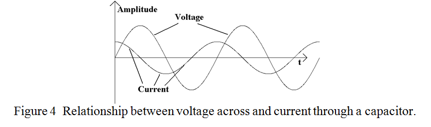
The current is said to “lead” the voltage by 900. In an inductor it may be shown that a very similar mechanism takes place but the voltage “leads” the current. The easy way to remember which is which is to remember what happens when you place a capacitor of several ?F across a power supply of a few hundred volts. There is a loud “splat” and a flash, rather like short circuiting the power supply, and the power supply voltage momentarily drops to zero. It soon recovers however and the capacitor is found to be charged to the power supply voltage. I.e. the large current occurred before and therefore led the large voltage. The reverse happens with an inductor. No current flows initially, but it builds up slowly, (to the power supply limit), and the voltage remains constant. I.e. the voltage leads the current in the case of an inductor.
When a capacitor is included in a circuit so that it is in series with other components, it is instructive to examine what happens when a charge is fed onto one plate. This will repel like charges on the opposite plate, which will then flow out of the opposite plate’s connecting wire. It is as if the charge had flowed through the capacitor. This is a convenient concept when dealing with AC as it enables one to treat capacitors as “transparent” to signal frequencies when following through a circuit diagram.
At high frequency alternating current, there is a loss mechanism in capacitors which is mainly associated with the dielectric, and special low loss materials such as mica and polypropylene are often used. Unfortunately, a really low loss dielectric for high radio frequencies has yet to be developed. It is a fortunate fact of nature that at even higher frequencies, in the order of 200 Tera Hertz, certain “glassy” materials have a region of minimum loss enabling optical fibres to achieve a loss in the order of 1dB per km.
Capacitors are available with values incrementing logarithmically, as in the “E” series, (e.g. E12 and E24), just like resistors. However, additional coloured dots or rings are sometimes included which can be confusing. There are several special types of capacitor, include variable capacitors for tuning applications, where one set of plates “meshes” with another, usually with air or a plastic between the plates. A variant of this type, intended for very high RF voltages, has both sets of plates sealed into a glass or quartz envelope which is evacuated and these are known as “Vacuum capacitors”.
PRAECEPTOR
| Back |
|---|