The Tuned Spark Transmitter
| Back |
|---|
I was interested to see whether a simple spark transmitter could produce significant amounts of RF power when tuned, and hence I adapted my car ignition coil based spark transmitter to include a tuned circuit effectively across the spark gap as shown in the circuit diagram of figure 1.
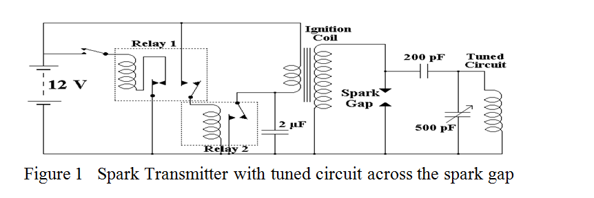
I have a set of very ancient “Premier Radio” plug-in coils, which, with a 500 pF tuning capacitor can tune anywhere between 0.6 and 31 MHz. I also have a small spectrum analyser with which to observe and measure the frequencies produced. However, the 200 pF isolating capacitor presented something of a problem as it has to withstand the peak voltage produced by the induction coil. After the rapid failure of several high voltage capacitors, I decided to measure the peak voltage and to this end I constructed a 1000 to 1 potentiometer which would not load the high impedance induction coil secondary winding too heavily. I used a 33 MΩ resistor in series with 33kΩ and fed the output from across the 33kΩ resistor to an oscilloscope. The peak voltage measured was across the secondary winding of the ignition coil was 30kV. With no capacitors of this rating in stock, I decided to make one in the tradition of historic experiments, i.e. a Leyden Jar. The resulting device is shown in figure 2.
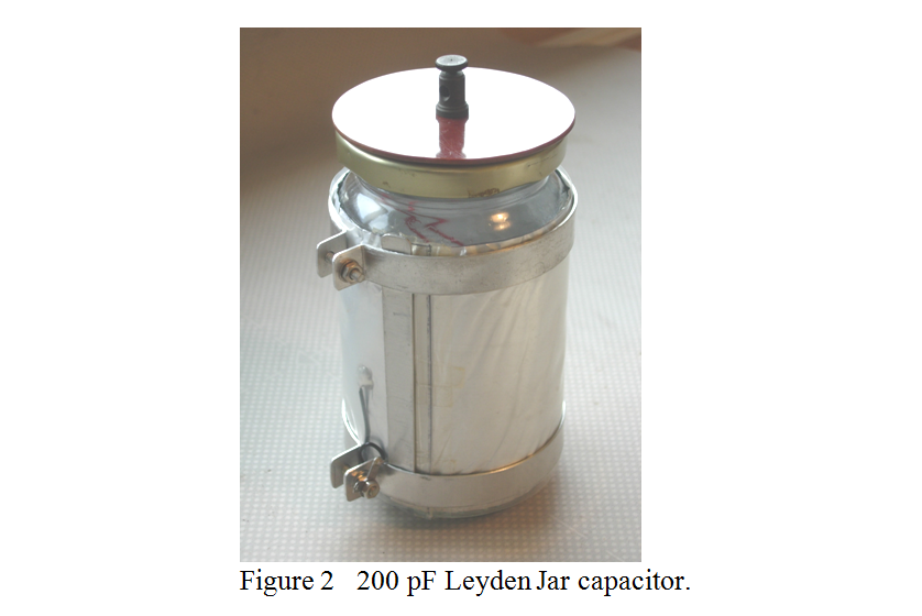
The glass of a clean jam jar formed the dielectric, and aluminium cooking foil was used for the inner and outer electrodes, the inner being kept in close contact with the glass by smearing the latter with Vaseline. The outer foil was kept in close contact by just wrapping it round the jar with a sheet of transparent plastic tightly wrapped over it. Making reliable contact with the foil presented a problem as I wished it to withstand very high discharge currents at high frequencies, so soldering seemed the best option. Special aluminium solder with highly active flux was necessary, but the scraping technique usually necessary with aluminium was out of the question as it tears the foil. In the end I found that I could tin the foil using a hotter than usual soldering iron applied to the foil before the solder. It was preferable to cut the foil to shape after I had successfully tinned a patch.
The end result of this tuned spark transmitter experiment was inconclusive in a quantitative manner but was never the less interesting. The reasons why no quantitative measurements could be made was due to limitations of the tuning capacitor. Although this was an old fashioned air spaced type, with reasonable spacing between the vanes, I found that which ever coil I inserted into the coil holder, even the highest frequency coil with only 3 well spaced turns on it, the capacitor sparked over internally over its full tuning range. So it seemed that about 1 kV of RF could be generated at any frequency within the tuning range. The spectrum analyser, coupled by means of a loop loosely coupled to the tuning coil, showed an extremely broad spectrum up to about 100 MHz and it was difficult to distinguish the maximum although its shape did change as the tuning capacitor was adjusted. This aspect of the experiments has not been pursued further.
While on the subject of simple spark transmitters, there are a couple of similar historic devices worthy of mention. It was known by 1908 that the type of spark greatly influenced the amount and purity of the RF produced. This is because, after the initial half cycle of RF, the ionised air in the spark gap damps the free oscillations in the tuned aerial circuit, and it was reasoned that it would be better to quench the spark after the initial discharge and so isolate the aerial circuit from the damping influence of the spark. Various methods were used with success. These included blowing the spark with a blast of high pressure air, using multiple small spark gaps in series with cooling insulators immediately adjacent to them, and using a rapidly rotating toothed wheel as one of the spark electrodes. This latter produced a pleasant and high pitched “singing note” on reception, and was known as the “Singing Spark”. If the wheel was rotated fast enough and the wheel had enough teeth, the singing note could be taken above the range of audibility and nearly pure CW could be produced, though this wasn’t much use for sending Morse when they only had envelope detectors in their receivers. It did however inspire the first attempts at the transmission of voice, and this was achieved by connecting a carbon microphone in series with either the aerial or the earth. I have tried this technique with a simple single valve oscillator and it certainly works, although the depth of modulation with an old GPO type microphone was only about 10%.
It had long been known that an electric arc, as was used in theatre spot lights and search lights, had a negative resistance characteristic, i.e., the more current put into the arc, the lower was the voltage across it, and attempts were made to use this as a generator of pure Hertzian waves. However, the maximum frequency which could be generated using the ordinary carbon electrodes was a high audio frequency. It was left to Poulsen in 1917 to generate higher frequencies, and this he did in a rather precarious manner by striking the arc not in air but in a hydro-carbon vapour. With the later addition of a transverse magnetic field and water cooled copper electrodes he eventually generated significant amounts of RF power up to 100 kHz. Poulsen arcs almost replaced the fledgling vacuum tube generators for a year or two as high power single frequency RF carrier wave sources. In fact many of the early experiments in modulating carrier waves with voice were conducted using Poulsen arcs.
Another successful technique for producing really high power RF, in the order of tens of kilo watts was the multi-pole high speed alternator. Some of these machines had up to 600 poles, were 6 feet in diameter and rotated at several thousand RPM, but their use was fairly short lived and they were soon overtaken by the constantly improving performance of high power vacuum tubes. Even to-day, there seems to be no substitute for the thermionic vacuum tube for powers of over about 100 kW at frequencies above a Megahertz.
In the next part I will describe the start of thermionics and solid state detectors.
| Back |
|---|
John G0NVZ