| Back |
|---|
Introduction
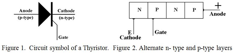
A Thyristor, (sometimes called a Silicon Controlled Rectifier, or SCR) is the solid state equivalent of a Thyratron, and is used for the same purposes. These purposes include as switchable rectifiers in regulated power supplies, as “crow-bars” for over voltage protection, and as fast switches in pulse forming circuits. The thyristor is a three terminal device like a transistor, and like a transistor the current through it is controlled by its base current However, unlike a transistor, when it is turned on it stays on until the supply voltage is removed. The three terminals are termed Cathode, Gate, (effectively the base of a transistor), and Anode, and its circuit symbol is shown in figure 1. Unlike many other circuit symbols, this one does not give much of a clue as to how it works.
Structure
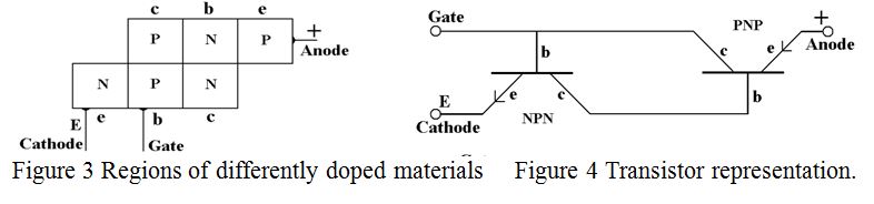
The Thyristor is a four layer device with alternate layers of p-type and n-type semiconductors as shown in figure 2. The cathode, (normally earthed), gate and anode, (normally positive), are indicated. In previous AB INITIO articles, the functioning of a semiconductor diode and a bipolar transistor were explained, and use is made of these explanations in the following. The important thing to remember is that positive current normally only flows from a p-type to an n-type region. An exception to this occurs when electrons are injected into the n-type region from an adjacent conducting p-n junction, as in the case of a transistor. It can be seen from figure 2 that a thyristor contains the elements of both an n-p-n and a p-n-p transistor. Starting from the left, the first three regions look like an n- p-n transistor and the last three look like a p-n-p transistor. It might be more appropriate to re-draw it as shown in figure 3, or for those more familiar with conventional transistor circuitry, as figure 4.
Operation
If a negative voltage is applied to the anode of the device, (i.e. to the emitter of the p-n-p transistor, far right in figures 3 and 4), the voltage sees a reverse biased diode and no current flows through the device. If a positive voltage is applied to the anode, (emitter of the p-n-p transistor), the voltage is transferred to the base of that transistor, (current flows easily from ‘p’ to ‘n’ of that transistor), and hence to the collector of the n-p-n transistor. However, once again no current can flow through the device to earth since the n-p-n transistor is in an “off” state. This is because, (at this stage), the base of the n-p-n transistor, (which is the Gate of the thyristor) has no voltage applied to it. In summary, no current flows and the thyristor remains turned off.
However, if a positive pulse is now applied to the Gate, turning the n-p-n transistor ‘on’, then current flows from the positive rail into the base of the p-n-p transistor, (turning it ‘on’), through the n-p-n transistor to earth. Turning the p-n-p transistor ‘on’ effectively connects the base of the n-p-n transistor to the positive rail, rendering the original positive pulse superfluous and both transistors remain ‘on’. The Gate then has no control over the current. The device can only be restored to its non conducting state by removing the positive supply.
Practical considerations
A typical application is as a safety “crowbar” across a variable but regulated power supply and this application will be described as an example.
Much amateur equipment is designed to work with a 12V to 13.8V supply, but is often used with a power supply capable of a higher voltage. It is all too easy to “turn the knob the wrong way for a few seconds” on the power supply and damage the equipment. However, with a thyristor set to trigger at 14V across the output of the power supply, it is effectively short circuited if the voltage rises to that level. The supply must then be turned off and the knob re-set before normal operation can be resumed, thus saving the expensive equipment, (for example a transceiver). This is what a “Crowbar” circuit does. In performing its function, the crowbar has to survive a transient discharge of the power supply smoothing capacitors, which for a few microseconds may exceed 100 Amps. Thyristors therefore have to be designed to survive this sort of treatment and accordingly their internal ‘p’ and ‘n’ junctions are constructed fairly robustly. The penalty for such robustness is that they are not as fast as fast transistors and often take several micro seconds to go from initial triggering to full conduction. High current capability and very low “end to end” resistance when in the ‘on’ state are more important than speed. Thyristors are a most useful addition to one’s semiconductor armoury.
| Back |
|---|
PRAECEPTOR