AB INITIO
| Back |
|---|
A representation of a half wave dipole fed at its centre by a balanced feeder is shown in figure 1.
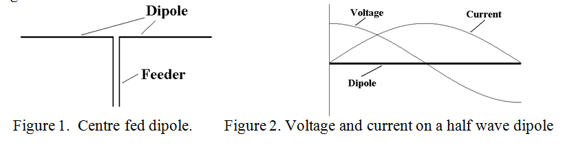
The RF current varies along the arms of a half wave dipole from a maximum at its centre, (where the radiation resistance is defined), to zero at its ends, and follows a roughly sinusoidal form. In a similar manner, the voltage along the arms also follows a roughly sinusoidal form but displaced by 90 degrees such that it has a minimum at the centre of a half wave dipole, (where the current is a maximum), and a maximum it its ends. This is depicted in figure 2, where the distance of the “graph lines” from the dipole represents the magnitude of the voltage and current. The effective impedance at any point along a half wave dipole thus varies from a relatively low value at its centre, equal to the radiation resistance, to a very high value at its ends in a roughly “tangent” manner.
A similar situation also applies if the dipole is a multiple of half wavelengths long and it is fed at the centre of one of the half wavelengths as indicated in figure 3. (In figure 3 only the current distribution is shown to avoid making the diagram too complicated). However in this case the radiation resistance is a little higher than 72 Ω and it rises progressively as the number of half wavelengths in the dipole is increased.
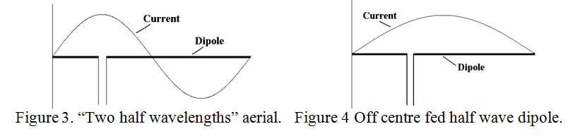
A dipole, (or any other kind of aerial), may not necessarily be fed at its centre, but it can still be matched to its feeder. An “off centre” fed half wave dipole is illustrated in figure 4. (In this context feeding “off centre” does not include “end-fed aerials” such as a random length wire or an “inverted L” shaped “Marconi aerial” where the feeder is intentionally part of the radiating system). When feeding “off centre”, i.e. feeding at other than a current maximum, the feeder will always radiate unless special measures are taken to prevent it. This statement needs explanation as follows.
Explanation by example. Consider a centre fed half wave dipole fed with RF power of 72W from a transmitter. The RMS voltage across the centre feed points will be 72V at a current of 1A. The voltages at the feed point will be “balanced” with respect to earth, i.e. at an instant in time one wire of the feeder will be at +36V and the other at –36V, the average value at the two feed points being zero, i.e. at earth potential.
Now consider a feeder with a characteristic impedance of 288Ω connected to the half wave dipole at a point where the impedance is 288Ω as in figure 4. For the same 72W, the RMS voltage across the feed points will be 144V at a current of 0.5A. The feeder is again matched to the aerial and no power is reflected back down the feeder in a differential manner, i.e. with equal and opposite currents. However, in a resonant system which has been allowed time to stabilise, (i.e. in about “Q” cycles from switch on), the average value of voltage at the two feed points is not zero, as it was for the centre fed dipole, but at some voltage, Vd say, appropriate to the sine wave distribution of voltage and current on a resonant dipole. The voltages on the wires of the feeder will therefore be Vd + 72 and Vd 72 volts. Although the feeder is matched to the aerial, this represents a common mode voltage on the feeder of Vd at the feed point. This voltage will force a common mode current to travel down both wires of the feeder in phase as though they were a single wire. Although it is possible for a wave to follow a single wire without radiating, (this is known as a Goubau line, or G-Line for short), such a wave is very loosely bound to the wire and any bends or other discontinuities, (such as passing through a wall or window), will cause it to radiate. Any unradiated wave will reach the transmitter. In this case, the Goubau wave is a common mode wave, so even if the transmitter is well matched to the feeder in the conventional sense, it will certainly not be matched for a common mode wave on the feeder. Thus almost all of the wave will be reflected and will travel back towards the aerial, setting up a standing wave which again will radiate. The only way to prevent feeder radiation from an off centre fed half, or multiple half wave dipole, is to incorporate a “choke” or “current balun” of correct feeder impedance in the feeder close to the dipole feed point.
A common position on a dipole for off centre feeding is one third of a wavelength from one end, at the longest waveband which it is intended to use. This presents roughly the same impedance for all “harmonically related” shorter wavebands as can be seen by an inspection of figure 5. Aerials which make use of this “one third of a wavelength effect” are known as “Windoms”, of which there are several methods of feeding. The original Windom aerial of the 1930s used a single wire feeder connected one third of the way along the aerial, the combination being “tuned against ground”.
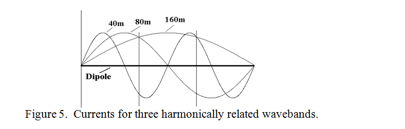
(It can be seen that the vertical construction lines drawn at one third and two thirds of the aerial length intersect the sine waves at similar phase points).
This near constant impedance at the “one third length points” is about 400 Ohms and is easily accommodated by twin parallel wire feeders. To prevent feeder radiation by the mechanism described above, a current balun needs to be inserted in the feeder at the aerial feed point. However, constructing a satisfactory current balun for a high characteristic impedance balanced transmission line feeder presents some difficulties. This is because the twin wire feeder is unshielded, so the usual practice of coiling the feeder into a few turns to form a common mode choke still allows significant capacitive coupling between the input and output of the balun, effectively bypassing it.
Of course, in some cases, some feeder radiation may be welcomed as it may provide some “null filling”. However, a radiating feeder usually implies “RF in the shack” with its own set of disadvantages unless some measures are taken just outside the shack to prevent radiation inside it.
| Back |
|---|
PRAECEPTOR