AB INITIO (Capacitors, Static aspects)
| Back |
|---|
A capacitor is an electronic component having the property of capacitance, that is, the ability to store electrical charge. But before we can appreciate what this means we must first be clear about a few fundamentals. Electronics is all about electrons, one of the three components of every atom which comprise all matter whether it be solid, liquid or gas. Individual atoms consist of a nucleus containing neutrons which have mass but no electrical charge, and protons, each of which has the same mass as a neutron but with a positive charge. Orbiting round the nucleus are an equal number of electrons to the number of protons, each of which carries an equal but opposite charge to that on each proton, thus making the atom electrically neutral. (This is “Bohr’s” model of the atom which is adequate for this simple explanation). In a conductor, some of the electrons in the outer orbits of the atoms are free to roam both within the conductor and into neighbouring connected conductors.
Theory
The unit of electrical charge is the “Coulomb” and each electron carries a charge of 1.6×10 19 Coulombs. Each electron fiercely repels any other electron but also fiercely attracts any proton. By convention, an electron is said to have a negative charge and a proton a positive charge. A conductor with more electrons than protons is said to have a negative charge and conversely if it has less electrons than protons it is said to have a positive charge.
In electro-magnetic theory, quantities and processes are often best explained by analogy, and the quantity and flow of water is often used. A suitable analogy to charge, (measured in Coulombs), is a gallon of water. The flow of electrons constitutes an electric current, (measured in Amps), which by analogy becomes gallons per second passing a given measurement point. The Amp is therefore a quantity of one Coulomb passing per second. Taking the analogy further, a capacitor is like a cylindrical or rectangular water tank with the height of water, (or pressure at the bottom), being equivalent to Voltage, (or potential for doing work), and the capacitance of the capacitor, (measured in Farads, symbol “F”), being equivalent to the cross sectional area of the bottom of the tank. (Note that the word “capacitance” is used rather than capacity as it does not mean “how much it can hold before it is full”. A capacitor is never “full” until it breaks down internally and sometimes spectacularly). A capacitor with a capacitance of one Farad is defined such that when the capacitor holds a charge of one Coulomb, the voltage across it is one Volt. It’s like saying, “when the tank has one gallon of water in it the height of water is one inch”. A one Farad capacitance is very large for radio purposes.
Practice
Now let us apply this understanding to realistic capacitors. The most basic capacitor consists of two flat parallel metal plates with an insulator, (frequently air), between them. The circuit symbol is shown in figure 1 which is a good representation of how it works.
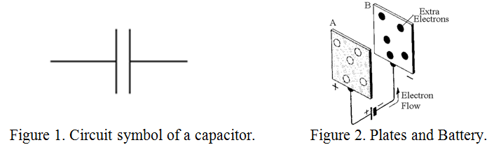
Consider the two metal plates connected to a battery as in figure 2. The battery
removes some electrons from plate A, leaving it positively charged and pushes them onto plate B, which becomes negatively charged. Very soon the electrons on the negative plate repel any further flow onto it from the battery and the current stops. A similar process applies to the positive plate. The capacitor is then charged to the battery voltage and if it is disconnected from the battery it will retain this voltage more or less indefinitely until discharged by connecting its plated together. The plates will attract each other due to their respective positive and negative charges and unless restrained will exert a squeezing force on the dielectric material between them. If now the plates are brought closer together, the electrons on plate B will still repel each other and try to escape via the connecting wire but they will also be attracted more strongly by the positive charges on the other plate, so the voltage between the plates will fall. This is exactly what would happen if the capacitance of the capacitor were larger. Thus, intuitively, we observe two effects:
1) The larger the plates the greater the capacitance, and,
2) the smaller the distance between the plates the greater the capacitance.
In fact the capacitance “C” is given exactly by the formula:
C = e0.ed.A/d (Farad)
Where C is in Farads, e0.is the dielectric constant, (sometimes called the permittivity), of free space, (equal to 8.85 × 10 12 Farad per metre), ed is the dielectric constant of the insulating material between the plates, (1 for air), A is the area of a plate in square metres, and “d” is the distance between the plates in metres. For example, two 10cm square plates separated by 1mm of air would have a capacitance of:
C = 8.85×10-12 × 0.01/ 10-3 = 8.85×10-14 ×103 = 8.85 × 10⁻¹¹F, or 88.5pico-Farad
I said above that a Farad was a large unit of capacitance. So also is a Coulomb a large unit of charge. In fact two separate charges of one Coulomb each, one metre apart exert a force of repulsion or attraction, (depending on whether they are of like or unlike sign), of about a million tonnes.
When a capacitor is included in a circuit so that it is in series with other components, it is instructive to examine what happens when a charge is fed onto one plate. This will repel like charges on the opposite plate, which will then flow out of the opposite plate’s connecting wire. It is as if the charge had flowed through the capacitor. I will not dwell on this point here but it is a convenient concept when dealing with alternating current which will be the subject of a future article.
Capacitance always exists between conductive objects, for example the plates and hence the terminals of the capacitor, but all conductive objects also have “self capacitance”. This depends on the size and shape of the object and, except for the case of a metal sphere, it is difficult to calculate. It is usually much smaller than the capacitance between objects and is usually ignored. For example, a 20cm diameter metal sphere has a self capacitance of only 11pF. Self capacitance can be regarded as capacitance to earth which is assumed to be a long way away.
In order to increase capacitance for a given physical size of capacitor, the dielectric filled space between the plates is often made very thin. However, this incurs the penalty of lower “break-down voltage”. The plates are often made of thin metal foil separated by paper and the whole rolled up into a cylinder. For even higher capacitance, one plate is sometimes made of metal and the other of a conducting liquid or gel, the dielectric then being a thin oxide insulating layer formed on the metal plate. These types are known as electrolytic capacitors and capacitances of many thousand of micro-Farads are obtainable. The capacitance of electrolytic capacitors can be increased even further by increasing the surface area of the plates by growing carbon nano-tubes on them. This is a very recent development and such devices are known as “super capacitors” Capacitances of 10s or 100s of Farads have been achieved. The break-down voltage of these exotic devices however is only a few volts. They have found application as back-up for batteries in Kinetic Energy Recovery Systems in F1 racing cars due to the high charge and discharge rates available via the dynamo/subsidiary electric motor.
The charge storage properties of more modest capacitors are used for smoothing the rectified output of power supplies, for separating AC from DC , and a host of other applications, but in all cases their basic mechanism is as described above.
What has been described in the foregoing is essentially the use of capacitors at DC. The use of capacitors with alternating current will be dealt with in a future article.
PRAECEPTOR
| Back |
|---|