| Back |
|---|
I have been asked to explain, in very simple terms, how a phase locked loop works. By ‘simple terms’ in this context, is meant that the reader is assumed to have no previous experience of digital circuits. Firstly, a phase locked loop forms the heart of several forms of “Radio Frequency Synthesiser”, which can be quite complicated. Hence this explanation is necessarily very basic and is just aimed at giving the newcomer to the subject a rough idea of how it works. To this end, only a single simple “flow diagram” has been included.
Incidentally, the radio frequency synthesiser should not be confused with the musical synthesiser with which it only shares the name. The former produces a single output frequency of crystal controlled accuracy and great stability, whereas the latter produces an audible tone with selected harmonics of adjustable proportions and duration, thus enabling it to simulate the complex sound of any instrument in an orchestra.
History
In the “Good old days” of Amateur Radio, (and virtually all commercial radio transmitters), separate quartz crystals were used for each transmitted frequency within the band. This ensured the highest possible frequency stability. In the case of radio amateurs, it also satisfied the GPO inspector that your frequency could not wander outside the allocated band. A licence infringement of this sort could lead to prosecution and withdrawal of your licence. I well remember buying my first crystal for my 160 metre home built transmitter at a London shop and enquiring whether its second harmonic fell within the 80 metre band. Its frequency was 1866kHz which I later “frequency doubled” for use on the 80 metre band.
In those far off days when one was confined to a single frequency, one called CQ and then announced that you were “tuning the band for a call”. If and when a reply came, it was on the other station’s own single frequency. The frequency of “fundamental mode” crystals could be “pulled” by a tiny amount by connecting a small capacitor in series or in parallel with the crystal to raise or lower the frequency a bit, (but only by about 1kHz per MHz). However, the military in Word War 2, (being less mindful of GPO regulations), introduced the concept of single frequency working using fairly stable “Variable Frequency Oscillators” (VFOs). This enabled “Nets” where a sizable cluster of stations could all communicate on the same frequency at fairly short notice. The same valve and tuning circuit was used whatever the transmitter frequency. On switching to “receive” the same circuit was used for generating the local oscillator frequency, but the tuned circuit was shunted by an additional capacitor or inductor to produce the changed Local Oscillator frequency. The stability of such ‘valve’ VFOs was adequate, even for man-portable operation using ‘Amplitude Modulation’, for frequencies up to the top of the HF band, (30MHz), but not much beyond.
New Requirements
In the 1960s, the increasing volume of aircraft flights necessitated many more frequencies in the civil aircraft band of 118 to 138MHz, where the channels were initially spaced 100kHz apart. Frequencies were selected by the pilot or co-pilot using “thumb wheel” rotary switches. Each numbered wheel was connected to a disk or “wafer” of what is sometimes known as a “Yaxley” type rotary switch containing up to 20 small crystals in separate cans on each “wafer”. Each digit of the required frequency, (for example 126.5MHz), had its own wafer, (eg 1, 2, 6, and 5), and crystals. These crystal frequencies were mixed in various combinations (with suitable filtering, also switched by the numbered wheel, to reject unwanted combinations), to produce the final output frequency. Scores of crystals were required. As air traffic increased and the channel spacing was progressively reduced through 100kHz to 50, 25 and to the current spacing of 8 1/3 kHz, this method clearly became unsuitable. The military also required ‘channelized’ communications, and this eventually lead to the frequency synthesiser we know today.
The Frequency Synthesiser
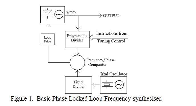
At the heart of the simplest form of RF synthesiser is the phase locked loop, containing a single crystal oscillator, a voltage tuneable oscillator, (sometimes called a voltage controlled oscillator, or VCO), a pair of digital “frequency dividers” (one for each of the above oscillators), a phase comparator, (more correctly called a frequency and phase comparator), and a “loop” filter. The following describes each of these sub-systems in turn.
The crystal oscillator needs little introduction. It provides an amplitude and frequency stable output of a few volts at any convenient frequency, typically 1MHz or 10MHz.
The voltage controlled oscillator comprises an amplifier with positive feedback whose frequency is determined by a resonant Inductance and Capacitance tuned circuit. However, the capacitor is variable, not by rotating its drive shaft as in a normal VFO, but by the use of a “Varactor”, sometimes known as a “Varicap”, whose capacitance is inversely proportional to the DC voltage applied to it. Thus the frequency of the oscillator may be varied anywhere within the design range by varying the voltage applied to the varactor. The output of the synthesiser is taken directly from the VCO for either the local oscillator for reception or the output frequency on transmission.
The Digital Dividers need some explanation. They rely on a lot of logical circuitry crammed onto a single multi pin chip. One of the simplest things digital circuits can perform is to count pulses. If an RF voltage is input to this chip, it can easily be arranged to count the positive half cycles and output only alternate ones, or one in 3, or one in any other number. In other words the chip can be programmed, (often by earthing the appropriate pins), to divide the input frequency by any whole number.
There are two digital dividers in the Phase Locked Loop, one, (fixed number divider), divides the output frequency of the crystal oscillator, and the other, (the programmable divider), divides the output frequency of the VCO.
The Phase Comparator is built around a mixer into which are put the “divided down” crystal frequency and the “divided down” VCO frequency. Most amateurs are familiar with “mixers”. When two frequencies are input to a mixer, the output contains the sum and difference frequencies of the input frequencies. In this case only the difference frequency is selected.
When the two input frequencies are far apart, the output frequency of the mixer is high and when the two input frequencies are close together, the output frequency is low. However, when the two input frequencies are identical the output is at DC. A small amount of “digital wizardry” sorts out the magnitude and sign of the DC output voltage which depends on the relative phases of the two inputs. For example, if the ‘divided down VCO frequency’ is higher than the divided down crystal oscillator frequency, the output is plus a few Volts. If it is lower, the output is minus a few Volts.
When the two frequencies are identical, the output stabilises at a voltage which depends upon the relative phase of the two inputs. This DC output is used to vary the output frequency of the VCO, (positive volts driving the VCO frequency down and negative driving it up say). However, the mechanism(s) of the “digital wizardry” are beyond the scope of this simplified article. The “Loop”, implicit in the name ‘Phase Locked Loop’, comprises the closed path:- VCO, Programmable divider, Phase comparator (mixer), Loop filter, back to VCO, and is shown in the simplified Block diagram of figure 1.
The Loop Filter is basically a low pass filter which “cleans up” the mixture of DC and difference frequency to provide the varactor which controls the VCO output frequency with a clean pure DC steering voltage.
‘In Principle’ Example
Suppose it is required to transmit on a frequency of 7,101kHz. Assume the crystal oscillator oscillates at a frequency of 1MHz, and its fixed divider is set to divide the input frequency by 10,000. The output frequency of the fixed divider, and one of the input frequencies to the phase comparator is therefore 100Hz. The other input to the Phase comparator is derived from the VCO. By turning the tuning knob, (which earths the appropriate pins of the programmable divider), this is set to divide its input frequency from the VCO by 71,010. This yields a lowish frequency which is compared with the 100Hz frequency in the comparator. The DC output to the loop filter depends of the difference between the divided down frequency from the VCO and 100Hz. If it is lower, the voltage is positive (say), if it is higher, the voltage is negative. This voltage is added to a bias voltage, (to ensure that the varactor of the VCO is within its working range), so steering its output frequency in the right direction until both the frequency and phase of the divided down signal from the VCO is identical to that of the 100Hz reference. In the above example, the output of the VCO is now 71,010 × 100Hz, or 7,101kHz which (say) is the required transmitter frequency. Moreover, in principle at least, this frequency has crystal controlled accuracy and stability. On changing from transmission to reception the programmable divider is rapidly switched to another divisor number differing from the transmission divisor number to produce the local oscillator frequency for the required Intermediate frequency.
Epilogue
Although frequency synthesisers could be designed like this, in practice they are usually more complicated to overcome a variety of problems. For example, in order that the Loop filter functions efficiently, its band width must be quite narrow, which leads to a long settling, or lock-in time. Also, the output frequency can only be moved in 100Hz steps, and choosing smaller steps even further increases the time to search and settle. To alleviate these problems, the “fixed” frequency divider is sometimes also made programmable, or the division is done in two stages. Sometimes a “double loop” is used etc. etc. In fact there is a variety of techniques used to enable current synthesisers to perform both fast and in small frequency steps as required by modern transceivers.
Again, it must be emphasised, that the above explanation only attempts to convey the basic principles of phase locked loops and their use in frequency synthesisers.
PRAECEPTOR
| Back |
|---|