| Back |
|---|
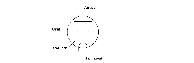
In a previous article the working of the thermionic diode, (which was originally produced by the then existing electric light industry), was discussed. This described how, when a thin filament, (usually made of Tungsten), was heated to incandescence by an electric current, some of the electrons comprising the filament current would “boil off” into the surrounding vacuum of the lamp bulb. This produced a “space charge” around the filament before the electrons eventually returned to the filament. However, if a metal plate, (sometimes called the “Anode” in similarity with battery terminology), were placed near the filament and connected through the glass envelope, a small current could be drawn from it if it were made positive relative to the filament by a separate battery. This form of diode, used by Ambrose Fleming in 1904, formed the basis of the rectifying detector of many early wireless receivers. An even more significant advance came in 1905 when Lee de Forest put a “grid” of wires between the filament and the plate, though he didn’t really understand its function. It was left to others to exploit the fact that a small negative voltage on the grid relative to the filament reduced the plate current significantly and could control it in a fairly linear manner; and so the Triode was born. The details of the operation are that the flow of negative electrons emitted by the filament and drawn to the positive plate but are repelled by the negative grid and squeezed into the narrow gaps between the grid wires. In this way, the plate current is controlled or regulated. An often quoted analogy is controlling the out-flow of water from a hosepipe by squeezing it with the foot by standing on it. At a relatively few negative volts on the grid, (depending on the fineness of the mesh of the grid), the electrons could be completely stopped from reaching the plate. This was known as the “cut off” voltage. The circuit symbol for a triode is shown in figure 1, which gives a good idea of its structure.
Development of the triode valve was rapid. The original filament was replaced by a hollow “cathode” enclosing the filament which was now called the “heater”. The cathode surface area was increased to increase electron emission, and the cathode surface was coated in substances which emitted electrons up to 100 times more efficiently than Tungsten. This led to lower heater and cathode temperatures, thus increasing heater life. The plate, (or “anode”), evolved from a flat plate into a cylinder completely surrounding the cathode and grid.
One of the important characteristics of the triode valve was that the grid took no current to control the plate current, i.e. it had a very high input impedance, whereas the plate, from which the output was usually taken, had a modest impedance, (change in plate voltage divided by change in plate current), of a few thousand Ohms. The triode therefore had huge power gain.
It was the triode valve which really gave rise to modern wireless technology, with amplifiers, oscillators and true CW transmitters. It made a complete break from the previous “all mechanical systems” using spark transmitters and coherer type receivers. The one big disadvantage of the triode was that, to make use of its high gain, the input had to be applied between the grid and the cathode, (which was usually earthed), and the greatly magnified output taken between the anode and earth. This meant that the input and output were coupled by the grid to anode capacitance, resulting in feed-back and instability, particularly at high frequencies. Derivatives of the triode were soon developed in which additional “screening” grids were introduced between the “control grid” and the anode, giving rise to the “Tetrode” and “Pentode”, but these are beyond the scope of the present article.
An important alternative to additional grids to reduce the problem of unwanted feed-back between output and input was to use the control grid as an earthed screen between the cathode and the anode. This required introducing the input signal into the cathode lead. This in turn meant that the input signal had to modulate the cathode current and hence the advantage of the extremely high input impedance was lost. However, power gains of several dBs were available in this “grounded grid” configuration with complete stability. In fact high power radio frequency amplifiers of many broadcast stations still use this technique.
Triodes have been made for many applications and in many sizes from “acorn valves”, little more than a centimetre in length for use in VHF receivers, through “disk seal triodes” which can operate up to about 10GHz, right up to water cooled giants two or three feet in height with outputs of mega watts for industrial applications and high power MF and HF transmitters.
One novel type of triode has low pressure inert gas introduced into its glass or ceramic envelope instead of a vacuum. This type is operated with its grid at a large negative voltage so that the anode current is cut off. When the grid voltage is raised so that anode current starts to flow, it ionises the gas and an avalanche effect occurs and a current measured in many Amps can pass between the anode and cathode. Such a device has been used to generate the time base in oscilloscopes, TV receivers and pulse radar systems and is known as a “Thyratron” and was the predecessor of the modern semi-conductor “Thyristor”.
| Back |
|---|