| Back |
|---|
Does Size Matter (in coaxial cables)?
Introduction
Everybody agrees that “Big coax”, has less loss for a given length than “Small” coax, (even though it is less convenient to use). Let us see why this is so. Every electrical circuit requires a “Go” and “Return” wire from its power source. In the mains wiring of a house for example, the “return” wire is often earthed at the junction box and therefore has zero volts on it. The same is usually true of coaxial cable where the braid or sheath or ‘outer’ is usually earthed and the ‘inner’ is live. The outer itself is usually covered in plastic to render the whole cable more or less waterproof. The cross-section of a typical coaxial cable showing the conductors is depicted in figure 1.
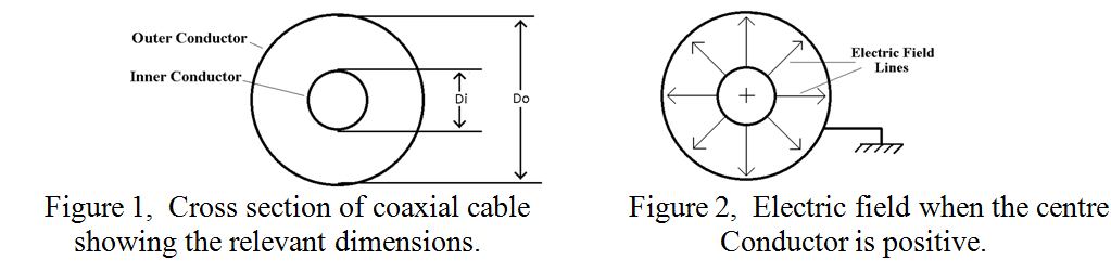
Current flows on the inner conductor (diameter Di), and in the opposite direction on the outer conductor (diameter Do). At any instant of time, and at any point along the coax, equal and opposite electric charges are present on the inner and outer conductors. These opposite charges attract one another so the current actually flows near the outer surface of the inner conductor and the inner surface of the outer. This uneven distribution is an aspect of the “Skin Effect” which was explained in more detail in the club newsletter of January 2014. Because of the potential difference between the inner and outer conductors, an electric field exists between them, and at the instant in time when a section of the inner conductor is positive, the electric field is in the direction shown in figure 2. Half a cycle latter, (when that section of the inner conductor is negative), the electric field is reversed and the field lines point inwards. In addition to the radial electric field, there is a circumferential magnetic field, (not shown in figure 2), everywhere perpendicular to the electric field. The wave in the space between the inner and the outer is therefore called a “Transverse Electromagnetic Wave”, (TEM).
The space between the inner and outer is usually filled with a low loss dielectric material, mainly to ensure that the inner remains in the centre of the outer when the cable is flexed, ie so that the conductors remain ‘coaxial’. However, the dielectric filling also has three important effects, It slows the wave down due to the refractive index of the material, it lowers the “Characteristic Impedance” of the cable, (discussed later), and it raises the Breakdown Voltage and therefore the peak power handling capability of the cable, depending on the breakdown strength of the dielectric material. (The value of Refractive Index, a term usually confined to optics, (usually designated ![]() or ‘n’), is the square root of the dielectric constant of the material, (usually designated
or ‘n’), is the square root of the dielectric constant of the material, (usually designated ![]() or ‘K’). The refractive index is also the reciprocal of the “velocity factor” of the cable).
or ‘K’). The refractive index is also the reciprocal of the “velocity factor” of the cable).
Coax is commonly used as a “feeder”, to transfer RF power between an RF generator and its load, for example from a transceiver to the aerial. The load, (aerial), has a certain feed point impedance, (72Ω for a dipole), and to ensure that most of the RF power is radiated from the dipole, and a minimum amount is reflected back along the feeder towards the transceiver, the coax feeder should have a fairly similar characteristic impedance to the load. (75Ω is usually considered near enough). In some circumstances, a matching transformer may have to be used, but this will not be discussed here.
Loss
The dielectric filling is sometimes made of a foamed plastic material, or in the form of intermittent spacers in otherwise “air filled” transmission line to reduce the dielectric loss. However, at all frequencies lower than “microwave”, most of the loss in coaxial cable is due to conductor loss in the inner and outer. The skin depth is the same in each, and as the same current is carried in each, the loss, (usually quoted in dBs per 100 feet or metres), tends to be concentrated more in the inner than in the outer, due to the inner having a smaller circumference where the RF current mainly flows. The loss can be calculated from the resistivity of the material, (usually copper or silver), the skin depth, (determined by the RF frequency), any loss in the dielectric, and the velocity factor.
Characteristic Impedance
This is determined fundamentally by the ratio of the inductance per unit length, divided by the capacitance of the inner to the outer per unit length. It is determined solely by the ratio of the diameters of the inner and the outer, and the dielectric constant, (K), of the material between them. For completeness, the characteristic impedance, Z (in Ohms), is given by:-

Breakdown Voltage
As the voltage on the inner conductor is raised, (assuming the outer is earthed), breakdown will start when the electric field strength exceeds the breakdown strength of the dielectric material, (for air this is about 3Megga Volts per metre). As electric field strength adjacent to a conductor carrying the voltage is inversely proportional to the radius of curvature of the conductor, this will occur near the surface of the inner conductor as its radius of curvature is less than that of the outer. Thus, the larger the coax cable or component for a given ratio of inner diameter to outer diameter, the more voltage (and thus more power) it can handle. In practice, even when using high dielectric strength materials, junctions between cables, and between the cable and other components such as connectors, involve air gaps. These often break down long before the theoretical limit of the dielectric is reached. When standing waves are present, breakdown will occur at the points where the voltage is a local maximum, all other things being equal.
Optimum designs (Lowest loss and highest power)
Let us assume that, for practical convenience, the maximum size, (ie the diameter of the outer), is fixed. It might be thought that raising the characteristic impedance of the cable used to transfer RF power, would lower the loss as the conductor resistances would then be a smaller proportion in comparison to the characteristic impedance. However, raising the characteristic impedance for a fixed size of outer conductor entails reducing the diameter of the inner conductor which increases its loss. The loss per unit length of cable is therefore a function of both the resistances of the conductors and the characteristic impedance of the cable, Z. It can be shown that, as a result of these two conflicting considerations, there is a ratio at which the loss is a minimum. This minimum occurs when the ratio is approximately 3.591, corresponding to a characteristic impedance of 76.653Ω for air filled cable. This is completely independent of the size of the coax or of the resistivity of the material from which it is made.
Again, assuming a given size of outer conductor, increasing the diameter of the inner conductor has two conflicting effects on the power handling capability:
a) It reduces the gap between inner and outer which increases the electric field and therefore the likelihood of breakdown between the conductors and,
b) It lowers the characteristic impedance, Z, which lowers the voltage on the centre conductor which lowers the likelihood of breakdown. Again, it can be shown that there is an optimum ratio of diameters of inner to outer to satisfy these competing factors which is 1.6474, corresponding to a characteristic impedance of 29.918Ω. These figures are also independent of the size or material of the coax.
Why 50 Ohms?
Following the taking of the British invented Cavity Magnetron to America as part of the “Tizard mission” in 1940, the Americans at the Massachusetts Institute of Technology set up what they called the ‘Radiation Laboratory’. This did extensive work on both waveguides and coaxial systems in an endeavour to develop microwave radar systems. They worked mainly with “air filled systems”, both because it has the lowest loss and because suitable low loss plastics were not yet available. Knowing the optimum impedance for lowest possible loss and for the highest possible power, they took the arithmetic and geometric means, (53.29 and 47.87 Ohms respectively), and looked for a compromise. They found that a convenient gauge of American wire and a common size of copper plumbing pipe had an electrical impedance of 52Ω, and they worked with this throughout the Second World War. Just why this figure migrated to the current standard of 50Ω is not clear. It could just be that the “mean of the above means” produces a characteristic impedance of just over 50Ω. The above ratios, (for minimum loss and maximum power), seem to be independent of everything. They were almost worthy of being engraved as concentric circles with diameters of these ratios on the gold plaque aboard the Voyager spacecraft, together with several other symbols of our humanity. They would then indicate to any alien civilisation who might encounter the craft, that the inhabitants of Earth could communicate by Electro-Magnetic waves.
So the answer to the original question in the title is Yes, size does matter. Both the relative sizes of the inner to the outer and the overall size affect many aspects of the performance of coaxial cables.
PRAECEPTORPostscript to article by Peter G3RZP
From a technical viewpoint, the ‘Does size matter?’ is correct. From a historic viewpoint, not exactly.
Following the taking of the British invented Cavity Magnetron to America as part of the “Tizard mission” in 1940, the Americans at the Massachusetts Institute of Technology set up what they called the ‘Radiation Laboratory’. We now know from the reminiscences of Sir Bernard Lovell that the Germans were well aware of the cavity magnetron, it having been patented in Russia in 1930. Apparently there are references to a Japanese one in 1938.
This did extensive work on both waveguides and coaxial systems in an endeavour to develop microwave radar systems. They worked mainly with “air filled systems”, both because it has the lowest loss and because suitable low loss plastics were not yet available. This isn’t strictly historically correct, although it is true that the air filled system has the lowest loss and that this was recognised at the time. Radiomart (G5NI) was advertising ‘Basset’s concentric cable’ in the T & R Bulletin in July 1939: that was rubber insulated flexible coax patented in 1936, but except for the improvement in materials, was much as we know coax today. The 1936 ARRL Antenna Handbook showed how to make very low loss coax by threading isolantite beads onto a 12AWG wire and crimping them in position, and feeding the result down lengths of 3/8 in water pipe to make about a 70 ohm feeder. The ARRL Handbook mentioned the technique even as late as the 1958 edition. But also in 1938, there was an article in the T & R Bulletin about low losses in polyethylene and polystyrene insulators by G2NR, who was a chemist involved in researching these materials for RF use. The 1938 Marconi-Ekco TF144 signal generator had a polyethylene insulated output cable to its dummy antenna. Polyethylene was in short supply in the early war years, and the RAF ‘Short Wave Communication Handbook’ cautioned against using it except where strictly necessary. PTFE (‘Teflon’) was discovered in 1938, although its use as a low loss dielectric came later.
Knowing the optimum impedance for lowest possible loss and for the highest possible power, they took the arithmetic and geometric means, (53.29 and 47.87 Ohms respectively), and looked for a compromise.
Interestingly, the German wartime standard – and for some years afterwards – was 60 ohms.
They found that a convenient gauge of American wire and a common size of copper plumbing pipe had an electrical impedance of 52O, and they worked with this throughout the Second World War.
10 AWG and 1/2inch pipe with 1/16 inch walls will give 52 ohms when a polyethylene dielectric is used. Without the polyethylene, it is 78 ohms.
73
Peter G3RZP
| Back |
|---|