Recap on the Thyristor
In a previous article, I explained how a thyristor worked. This is a transistor-like device in which the current through it, (between anode and cathode), is controlled by the thyristor gate. However, unlike a transistor, the “through current” is not proportional to the gate current in a linear manner. Instead, the current through the thyristor remains at zero until the gate current exceeds some critical value. The thyristor then passes a current only limited by the external circuit, i.e. it becomes a short circuit between its anode and cathode. It then remains in this short circuit condition, quite independent of the gate current, and can only be restored to its non conducing state by removal of the positive anode voltage.
The Triac
This is very like two Thyristors connected in anti-parallel. It has two connections (designated Anode 1 and Anode 2), between which the main current can pass in either direction, which is controlled by a gate. It therefore performs the same function as a thyristor but with alternating current. The “dimming process” is achieved by allowing conduction to start at a “variable point” within each alternating half cycle. At the end of each alternating half cycle, the supply voltage is zero which automatically resets the thyristor for the next half cycle. The “variable point”, (under the control of the rotary knob), is achieved by a resistance-capacitance phase shifter. This comprises a variable resistance and a capacitor in series, across the input mains supply. Because the voltage across a capacitor always has a 900 phase shift relative to the current through it, the phase, (and voltage), across the capacitor varies, (relative to the supply voltage), as the series resistance is varied. This variable phase voltage is applied to the triac gate to vary the triac “turn-on” point, and hence vary the portion of the AC mains cycle which is applied to the load.
Operation
This is best illustrated by a series of oscilloscope displays. Figure 1. shows one cycle of the local 50Hz 230V mains supply, the peaks being about +325V. (The horizontal straight line through the middle of the wave has been superimposed by the second ’scope beam to indicate the zero volts level). The wave shape is seen to be a not very good smooth sine wave. The flattened peak is mainly due to the large proportion of electronic equipment in the domestic environment which “creams off” current from the top of the wave. Common examples of this are domestic electric cookers adjusted to less than their maximum output, (as referred to above), and DC power supplies using rectifiers which only conduct when the instantaneous AC voltage supplied exceeds the voltage on their smoothing capacitor, (i.e. most DC supplies).
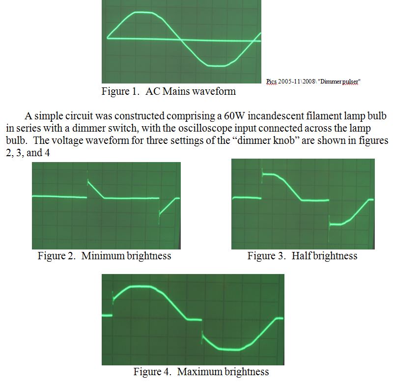
The superimposed “zero voltage” horizontal line has not been included on these last three images as sufficient of the waveform was at zero voltage to indicate the level. Notice two important things however. a) Even at the maximum brightness setting, there is still a portion of the AC waveform at the beginning of each cycle which is unused, so the lamp is not quite as bright as if the dimmer switch were not used, and, b) At each “turn on” point there is a burst of parasitic oscillation which, at its peak, reaches 50% above the AC peak, i.e. to nearly 500V.
PRAECEPTOR