| Back |
|---|
As explained previously, a short aerial will have a very low radiation resistance and any earth resistance will be effectively in series with it, resulting in most of the transmitter power being absorbed in the earth resistance rather than being radiated. The situation is indicated in figure 1 below, where Rr and C represent the radiation resistance and the capacitance of the aerial respectively, and Re represents the effective earth resistance.
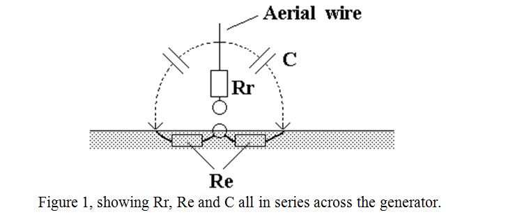
Rr is the only “useful” component but it is difficult for the current from the transmitter to flow through it because it is in series with the small capacitance, (large reactance), of the aerial wire. The capacitance of the antenna is sometimes made artificially larger, (smaller capacitive reactance), by the addition of a “capacity hat” at the top of the antenna. A similar reduction in the reactive component compared to the wanted resistive component can be achieved by including a series inductance near the middle or near the base of the antenna. This is particularly relevant to “whip” antennas. In any event, if Re is comparable with, or greater than Rr, then much or most of any current which can be forced through Rr is wasted in Re.
The problem often is knowing what the earth resistance really is. How then can we measure it? If you could have two identical earth connections, for example earth rods pushed to the same depth into identical types of soil, but separated by at least two rod lengths, then measuring the resistance between them should give exactly twice the resistance of either to the ground and finding the resistance of either would be easy. Unfortunately, finding identical soil types with similar dampness separated by several meters, is a near impossibility. It should also be noted that single earth rods do not make very low resistance earth connections. For a good earth connection, you really want as large a metallic object as possible buried as deep as you can reasonable go, which makes obtaining a pair of near identical good earths even more of an impossibility. However, all is not lost if you can manage three earths, however different they are. You can then measure all three earth resistances very accurately. If they are all quite good earths, you may decide to connect all three in parallel, or use one or perhaps two in parallel.
What you have to do is to make three separate measurements of resistance between the three pairs of earths rods. The problem of making three measurements and then deducing the resistance of each earth connection separately revolves around solving three simultaneous equations, but the solution turns out to be quite simple. Consider three earth rods or other forms of separate earth connection, labelled A, B and C as shown in figure 2 Three separate measurements of resistance can be made between the three separate pairs of earths. I.e., A to B, B to C and C to A. These resistances have been labelled c, a and b respectively, each lower case letter being opposite its upper case labelled apex in the manner of conventional geometry.
Figure 2 Three earth rods A, B and C with the resistances between them labelled a, b and c
The true “resistance to earth” of each connection, A, B and C is then given by:
A = ½ ( c + b – a)
B = ½ ( c + a – b)
C = ½ ( a + b – c)
i.e., the true earth resistance of each earth-rod to earth is given by: half of (the sum of the “adjacent resistances” minus the “opposite resistance”).
If you have the luxury of a fourth earth, a more complicated set of equations can be used from which you can estimate your measurement errors but I will not go into this at this stage.
Some important points.
The above technique only measures resistance. There may also be inductance in the earth wire, (which can usually be tuned out at any one frequency), but the wire may still radiate or pick up interference. The lowest measured resistance does not necessarily mean the best earth from an RF point of view, particularly if the earth wire does not go directly to earth. For example, a low measured resistance can usually be obtained by using the mains earth of a three pin plug, or a central heating radiator, but putting RF current into the mains wiring or into the central heating system may cause BCI and/or TVI.
When using a “real earth”, i.e. one connected to a buried conductor, make the measurements using AC rather than DC. I.e., don’t use a multi-meter on its Ohms range which uses DC. Measure AC Volts and AC current separately and calculate resistance by Ohm’s Law. This is necessary because slightly dissimilar buried conductors, or even identical conductors in slightly different soil patches, can act as a voltaic cell and will give erroneous measurements at DC. Also, direct current causes rapid polarisation of the earth conductors, considerably changing their resistance to the real earth. This can be observed by using a single cell battery and a milliamp meter between two buried earth rods. The current will be observed to change within the first few seconds of the current flowing. Use AC from a small mains transformer with an output of between 6 and about 20 Volts, and use an old fashioned passive analogue meter like an AVO to measure current in preference to a digital meter, particularly if measuring earth rods some distance apart. The pick-up from powerful Medium Wave stations by the connecting wires usually upsets the accuracy of most digital meters.
Don’t assume cold water pipes are a good earth. They are not as good as they used to be! The reason is that in many cases lead or copper pipes have been replaced by plastic, but even where a metal pipe is seen to go into the ground, the metal may not be continuous to the iron water-main in the street. In my area they have recently inserted about half a metre of blue plastic pipe between the metal pipe which runs under my front garden, and the street metal pipe, “just in case I need a water meter fitted at some stage”! So my water-main earth is now only 20 feet of shallowly buried metal pipe in the front garden instead of tens of miles of buried iron pipe which it was several years ago.
Finally, although the mains earth is undesirable from an RF point of view, it does provide a useful third (or fourth) earth to make up the numbers when making measurements and it usually has a very low resistance of less than one Ohm as opposed to earth rods which usually have a resistance to earth of tens of Ohms.
| Back |
|---|
John, G0NVZ