| Back |
|---|
Introduction
This is a two part article about some of the uses and design problems of Baluns. But first of all, what is this strange word ‘Balun’? It is formed from a contraction of the words “balanced to unbalanced transformer” and its primary purpose is to convert a balanced input to an unbalanced output, or vice versa. A balanced input is one where the two wires of a feeder, (sometimes called a transmission line), are both live and have equal status and carry equal and opposite voltages and currents, as for example to or from a well placed dipole. An unbalanced feeder is one where its two wires carry equal and opposite currents but are not at the same voltage. An example of this is a coaxial cable feeding a radio receiver, where one wire, the braid, is earthed and the other wire, the centre conductor, is “live”. A Balun may also be called upon to change the impedance from that of its input to that of its output. A typical example might be to change from 50W (in coax) to 200W (for a folded dipole in a Yagi array), but impedance transformation is a secondary purpose. This article only deals with the main types of “Wire Balun”. There are other types, mainly used at microwave frequencies, which employ other techniques involving open circuit or short circuit “quarter wavelength structures”.
Baluns are sometimes classified into two main types: Choke Baluns and Transformer Baluns, (these are also called Current Baluns and Voltage Baluns respectively). The choke or current balun attempts to force the currents through its output terminals to be equal in magnitude and opposite in direction. The voltage or transformer balun attempts to force the potential difference between its output terminals to be equal in magnitude and opposite in polarity with respect to the ground. Strictly speaking, a choke balun can only have an impedance ratio of 1:1, but a transformer, or voltage balun can have other ratios. (The impedance ratio of a transformer is the square of its primary to secondary turns ratio).
The 1:1 Choke or Current Balun
The simplest type of 1:1 choke balun comprises the two wires of the transmission line or feeder being wound together into a coil. If the ‘go and return’ currents of the transmission line are equal and opposite, then the magnetic fields of the two wires cancel and the fields ‘do not see’ the inductance of the coil in which they both take part. Any unbalance current between the lines sees the inductance of the coil and is rejected.
In practice, a 1:1 choke balun often comprises a few turns of coax wound into a flat coil with the turns taped together, or wound on a ferrite toroid as shown in figure 1a. It can also be a straight piece of coax with a tight fitting ferrite collar. When wound on a toroid, it is sometimes wound as in figure 1b to reduce the capacitive coupling between the input and output connections. The circuit symbol for such a device is shown in figure 1c.
(a) 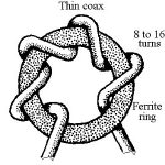 (b)
(b)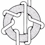
(c) 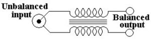
Figures 1a, b & c. Simple choke baluns comprising coax wound on a ferrite ring.
Because this type does not force the output voltages to the aerial or other load to be symmetrical relative to earth, (and because they are still in coax which is an unbalanced transmission line), WA6RDZ, has suggested that this configuration should be called a “Sorta-balun”.
The Balun concept
In principle, a balun is just like a transformer, connected as shown in figure 2.
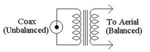
Figure 2. Isolated coils balun.
In principle, complete isolation between the coax coil and the aerial coil can be achieved if the coils are mechanically separated but are both wound on a magnetically continuous iron or ferrite core. However, to achieve a broad bandwidth, (say between 1.8 and 30MHz), the higher number of turns on the windings required for the low end of the frequency range means that the uncoupled or “leakage inductance” is rather high for the high end of the range. Currently available low loss ferrites suitable for radio frequencies do not have a high enough magnetic permeability on their own to make the ratio of mutual to leakage inductance of such a “conventional transformer” design sufficiently high. The usual resort is therefore to “bifilar wind” the two coils connected to the coax and aerial respectively. The action can be visualised as transformer coupling, making use of the ferrite at the lower frequencies, and proximity coupling at the higher frequency end of the range. (Bifilar winding means twisting the wires of the primary and secondary coils together and winding them as a single coil).
However, even bifilar wound coils, wound on a high permeability core have their problems because coils with sufficient turns to be suitable for the LF end of the above range have considerable capacitance between the two windings, (typically between 50 and 100pF). The coupling is therefore electromagnetic rather than purely magnetic. Such a bifilar wound device is sometimes known as a transmission line transformer. Although this ensures very tight coupling, the balanced output is not truly balanced. One end of the ‘unbalanced winding’ is necessarily connected to the outer or earthed shield of the coax, and the other end is connected to the centre or live wire. Thus the ‘balanced winding’ which feeds the dipole, (for example), is fed asymmetrically, one side having capacity to earth and the other, in addition to the magnetic coupling, having capacitive coupling to the live core of the coax. What is needed is true symmetry relative to earth, while maintaining tight magnetic coupling. This can be achieved by adding a third winding, trifilar wound, and using these windings as an “auto-transformer” as shown in figure 3.
Figure 3 Trifilar wound 1:1 auto-transformer.
An auto-transformer shares some of its windings between primary and secondary, thus ensuring the tightest possible coupling between those windings which are in common. Two coils are connected to the coax and two similar coils are connected to the aerial, so, (in this case), the transfer impedance ratio is 1:1.
A more detailed look at this configuration will be explained next month in part two.
PRAECEPTOR
| BACK |
|---|
| Wire Baluns (Part 2) |