AB INITIO
| Back |
|---|
To understand the reason for this you have to know a bit about inductance. Inductance is the property of a component to resist a change in current through it. Such a component is called an Inductor and it often consists of a coil of wire, sometimes wound on a ferromagnetic core. Inductance works by inducing a “counter emf” in the opposite direction to the applied emf, (emf = Electro Motive Force, measured in Volts),. This counter emf is proportional to the rate of change in the current through the component. This is described formally by Lenz’s Law which states: “The direction of an induced current, (if one were to flow), is such that its effect would oppose the change in magnetic flux linked to that circuit”. Even a straight wire has inductance, and Lenz’s Law still applies.
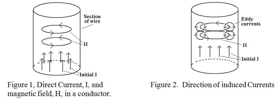
Consider a length of wire conductor with a Direct Current, I, initially evenly distributed across the cross section, entering at the bottom as shown in figure 1. By Maxwell’s Right Hand corkscrew rule, the magnetic field, H, generated by this current is in the direction also shown in figure 1, ie it forms closed loops inside the wire. Of course the magnetic field produced by the current is also produced outside the conductor, where it falls away with increasing distance from the current carrying conductor. It is this external field which is normally considered when understanding and designing transformers, dynamos, motors etc. However, here we are going to consider the magnetic field inside the conductor.
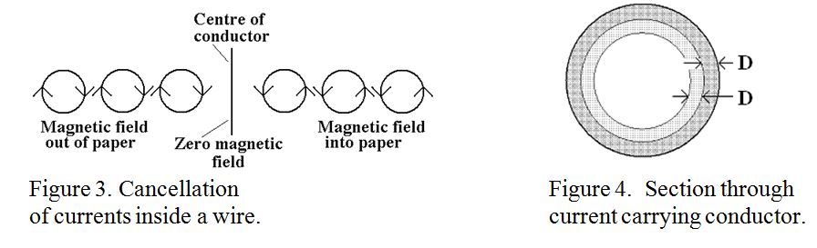
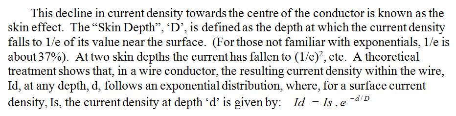
Radio Frequency currents are of course alternating currents, and a changing and reversing current will produce a changing and reversing magnetic field. This is where magnetic induction and Lenz’s Law comes in. Consider a “snapshot” at an instant in time when the current is increasing in an upward direction as shown in figure 2. The changing magnetic field inside the wire will produce currents encircling the magnetic field as shown in the figure. It is seen that the current flows downward inside each magnetic loop and upward outside it. The magnetic loops are not just those shown, but exist from the centre of the wire to its periphery. Now consider a magnetic loop, (not drawn), inside one of those drawn. It will have the same shaped current as that drawn, but its “upward” current will tend to cancel the downward current of the original outer magnetic loop, and so on from the centre of the wire right out to the periphery. The cancellations along a horizontal diameter of the wire are illustrated in figure 3. The net result is that current cancellation occurs everywhere inside the wire except at the periphery.
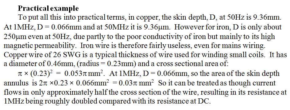
The net result is that over 98% of the current will flow within a layer 4 times the skin depth from the surface. This is quite distinct from the behaviour of direct current which is usually distributed evenly over the cross-section of the wire. An impression of the cross section of a wire showing the current density as shading density at two skin depths is shown in figure 4.
The actual skin depth depends in a slightly complicated way on the conductivity and magnetic permeability of the conductor and on the frequency of the current. As might be expected, inductive effects increase with increasing frequency. The higher the frequency, the thinner the skin depth, effectively reducing the cross section of the conductor, and thereby increasing its resistance. As a matter of fact, the skin effect and the resulting exponential decay of current with depth from the surface of a conductor also applies to a conducting reflector plate when a plane wave impinges upon it.
As the bulk of the current flows within the first skin depth, the quite accurate assumption can be made, when assessing the resistance of a wire, that the current flows uniformly through a layer of thickness D based on the DC resistivity of that material. We can therefore assume a cross-sectional area for conduction approximately equal to D times the conductor’s circumference.
PRAECEPTOR| Back |
|---|