| Back |
|---|
A dipole in free space, fed at its centre by a balanced feeder, can radiate all the RF power fed to it with no radiation from the feeder. Such a system is illustrated in figure 1.
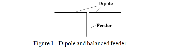
A dipole is a “resonant” aerial and its first “self resonance” is when its total length is approximately half a wavelength. The maximum current is then at its centre. The voltage between the two arms of the dipole at the centre feed point, divided by the current at this point defines the radiation resistance, which for this simple case is approximately 72 Ω resistive. If symmetry of the dipole relative to its surroundings and to earth is maintained, the dipole is said to be “balanced”. If a balanced feeder, (i.e. one having two closely spaces wires of equal diameter), is designed to have a “characteristic impedance” of this value, (72 Ω ) then the feeder is said to be matched to the dipole. In this case all the RF power supplied from the feeder is absorbed by the dipole and is radiated. I.e. no power is reflected back down the feeder. The voltages and currents in the two wires of the feeder will be equal in magnitude but in antiphase and the feeder is said to be in “differential mode”, i.e. there will be no “common mode” current, that is, no current flowing in phase down the two wires of the feeder.
A common method of feeding a dipole is with coaxial cable. This is very convenient because coax consists of a “live wire” in the centre and an earthed shield around it, so confining all the RF to the inside of the coax, at least until it reaches the aerial. The problem of feeding an aerial with coax is that coax really consists of three wires not two. Due to the “skin effect”, the inner and outer surfaces of the outer conductor, behave at RF as two separate surfaces which can support two separate currents. So what happens is that the RF currents sent up the coax on transmission consist of current on the outside of the inner conductor and an equal and opposite current on the inside of the outer conductor. On reaching the dipole all the current on the inner conductor is transferred to one limb of the dipole, but the current on the inside of the outer conductor splits between the other limb of the dipole and the outer surface of the coax. The currents are illustrated in figure 2, where the intended currents are shown as I1 and I2, but the unintended current on the outside of the coax is shown as I3.
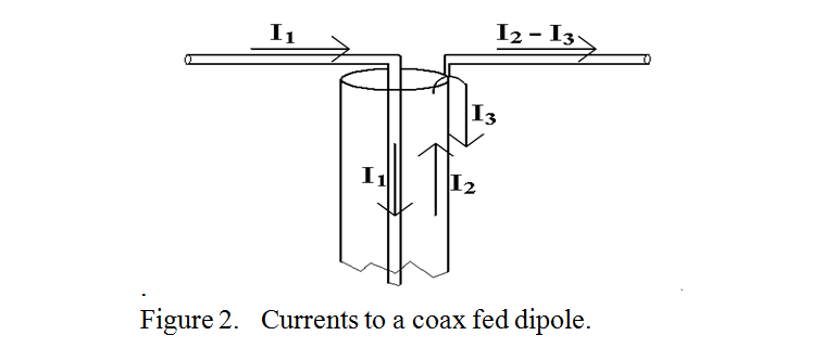
This current on the outer of the coax radiates with its electric field lines running between the coax outer and the “live” limb of the dipole. In effect the coax is feeding two aerials in parallel, the two dipole arms, and the outer shield of the coax to the live limb of the dipole. This has three main effects. Firstly the coax has RF on its outer surface which may lead to RF in the shack. Secondly, it distorts the radiation pattern from the usual “figure of eight” pattern usually associated with a dipole, and thirdly feeding two aerials in parallel results in a lower aerial feedpoint impedance than that of the dipole alone of 72 Ω. The first is definitely a disadvantage, but the second and third may be used to advantage. With a simple dipole, (assumed horizontal), the radiation pattern is horizontally polarised and it has nulls in it in the “end-fire” positions. When using a simple dipole one is not usually concerned with radiating in a particular direction but one would like at least some power to go almost everywhere. This is to some extent achieved by the feeder radiation which tends to fill in the end-fire nulls with vertically polarised radiation. (After the radiation has been scattered off the ionosphere its polarisation tends to be immaterial as it gets scrambled). If avoiding RF in the shack is the prime consideration, then it would seem that a 72 Ω coax feeder, plus some means of preventing current on the outside of the coax, (fitted adjacent to the dipole feed point), would be desirable. Such means is accomplished by a “Balanced to Unbalanced” transformer, known as a “Balun”, of which there are several types but these are beyond the scope of this discussion.
Although 72 Ω (or 75 Ω coax is available, it is mainly used in audio systems and for connecting television receivers to their aerial and is not used much by the amateur fraternity. Instead, 50 Ω is commonly used. This is where the third effect described above may be taken advantage of. The “unintentional” aerial comprising the outer of the coax and the limb of the dipole connected to the coax inner forms another aerial connected in parallel with the true dipole as observed above. This lowers the feed point resistance to nearer 50 Ω so that the Standing Wave Ratio on the feeder is rather better than the 1.5 to 1 which might have been expected from a 50 Ω feeder connected to a 73 Ω load.
As a matter of interest, the reason that 50 Ω characteristic impedance has become a standard has nothing to do with antennas. It is a rough compromise between two other requirements, minimum loss and maximum power handling. It can be shown that the conductor loss and the characteristic impedance of coax are both related to the ratio of the diameters of the inner to the outer conductors and that the loss is a minimum when this ratio is 3.591 to 1, whatever the conductor material or the kind of dielectric between them. In “air filled” coax this ratio corresponds to a characteristic impedance of 76.627Ω
In a similar manner, it can be shown that the peak power handling capability of coax reaches its limit when the electric field across the dielectric between the inner and outer conductors causes the dielectric to break down. The minimum electric field for a given power occurs when the ratio of inner to outer conductors is 1.6474 to 1. In “air filled” coax this ratio corresponds to a characteristic impedance of 29.92 Ω. The geometric mean of 77 and 30 is 48.06, and the arithmetic mean is 53.5, so it was decided to standardise on the nearest round figure of 50 Ω. In any case, as often as not, dipoles are accompanied by other resonant elements such as reflectors and/or directors which can change the dipole’s radiation resistance by a factor of up to about three. So there is no particular merit in standardising on an impedance suited to a dipole alone. 50 Ω has remained an industrial and international standard for the characteristic impedance of coax since the early days of Radar during the second World War.
| Back |
|---|
John, G0NVZ