AB INITIO
Back
Power at the higher frequencies Part l
History
Since the earliest days of investigation into electro-magnetic waves, scientists have wanted to understand and exploit the full spectrum of such waves. At one time wavelengths of less than 200 metres were not considered of much use for communication. However, it should be remembered that even the earliest experiments by Hertz with prisms of paraffin wax were conducted with what we would now call microwaves. He generated these by high voltage sparks between metal spheres. After the invention of the triode, sustained coherent E-M waves were readily available, and the quest was on for better transmitters and receivers at shorter and shorter wavelengths. One of the driving forces of this quest was the narrower beam-widths and higher gains which could be obtained from more sophisticated antennas than single pieces of wire, even though it was recognised that reliable communication would be limited to “line of sight”. Also, the broader bandwidth which was potentially available at higher frequencies could be used for “up and coming” television systems. As the “day-light short wave bands” were discovered and world wide communication and broadcasting evolved, such as the Empire broadcasting service, Curtain Arrays directed to various parts of the empire were developed. These could be replicated in miniature at the higher frequencies. A significant development, although it was not recognised at the time, (1926), was the invention by Yagi and Uda of Japan of what we now call the Yagi aerial. In fact, the Japanese failed to make use of it throughout the second World War although it was widely used by the British and Americans.
Small Valves
One of the advantages of the higher frequencies is that fixed communication links can be set up which don’t need much transmitter power because of the narrower beam and higher gain of the aerials. Nevertheless, the search was on for efficient generators of frequencies of hundreds to thousands of Megahertz. In both transmitters and receivers it was felt that the smaller the dimensions of the components of thermionic valves, the better they were at handling the shorter wavelengths. This belief had some foundation. The electrons emitted by the cathode travel relatively slowly, (compared to the speed of light), to the anode in a valve. They are modulated or controlled by the grid. It is no good if, while the electrons are in transit, the grid changes from assisting the electrons on their way to impeding them. The net result is neither. In other words, such devices fail to work properly if the time between positive and negative half cycles of the wave becomes comparable to the transit time of the electrons. Hence the mantra of “miniature size for miniature wavelengths”. However, miniaturising the valve was not compatible with increasing the power. The first breakthrough to this conundrum was made by two Germans, Barkhausen and Kurz in 1920, although it is not clear that they understood the implications of their invention at the time. In their experiment, they made the grid of a valve electrically positive and the anode negative. They were fortunate in choosing a valve with a fairly open grid structure. The negative electrons emitted by the cathode accelerated towards the positive grid but overshot. They were then decelerated by the negative anode and sent back towards the cathode where they were again reversed in direction. This oscillatory motion continued until they were eventually intercepted by the positive grid. The frequency of oscillation was entirely controlled by the geometry of the valve and the voltages applied to the grid and anode. They were making use of the electron transit time which had been such a disadvantage in earlier experiments. However, B-K oscillators, as they were known, were notoriously unstable and short-lived but they were used for numerous experimental purposes including early attempts at radar. Although capable of producing frequencies of several hundred MHz, and capable of lighting small lamps across a Lecher Line, (which formed part of the circuit), powers of more than a very few watts evaded them. The B-K oscillator was sometimes known as the Retarded Field Triode. (Technical Note: a Lecher Line is a parallel wire transmission line comprising a pair of closely spaced uninsulated wires which can be bridged by, for example, a short circuit, a small filament lamp bulb or a neon tube for demonstrating the presence of RF power).
Receivers were less of a problem. Miniature valves, some known as “Acorn Valves” were available, and even semi-conductor diodes (using copper-copper-oxide junctions) for mixers were used. However, these latter were limited to use at the low hundreds of MHz because of their high junction capacitance. They were later replaced by Tungsten wire-Silicon diodes in the fashion of previous generation “crystal and cat’s whisker” detectors. Although relatively small power was available from small valves, it was more than adequate for the local oscillator in reasonably efficient “superhet” receivers. The real breakthrough was the using of transit time to advantage, and this took two main directions: Klystrons and Magnetrons.
The Klystron.
It was realised that the electron stream, prior to its time in transit, could be velocity modulated instead of amplitude modulated. Moreover, during its transit time, velocity modulation became density modulation, which was, as far as their collection system was concerned, the same as amplitude modulation. It works like this. If the velocity of electrons in a stream can be varied about their mean velocity, then during their transit time, the faster electrons will catch up those in front and the slower ones will fall behind, so “bunching” will occur. Such velocity modulation could easily be achieved by passing the stream of electrons through a narrow space containing an alternating electric field at the required frequency, such field being parallel to the electron stream.
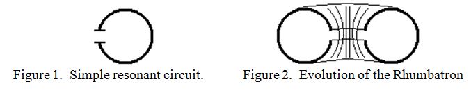
Another important innovation for the higher frequencies was the evolution of a simple L-C circuit into its simplest form: a ‘C’ shaped ring. Thus the body of the ‘C’ acts as the inductance and its open ends act as the capacitance across which the electric field would be at its maximum. A “C” shaped resonator is shown in figure 1. It was then a simple matter to evolve this into a slit hollow toroid. The slit hollow toroid cavity is sometimes called a “Rhumbatron”. An attempt to depict half of it is shown in the “cut away” drawing of figure 2.
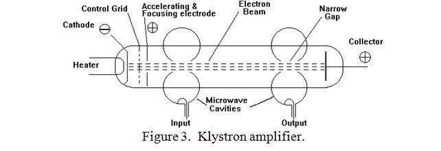
When the Rhumbatron is energised at its resonant frequency, the electric field is at its maximum intensity across the slot. Such a structure, placed with its axis coincident with an electron stream forms the ideal velocity modulator. The velocity modulated electrons become amplitude modulated as they drift in a field free region towards a second rhumbatron. This then becomes electrically energised by the periodically bunched electrons and amplified RF power can be extracted from it. The whole assembly is called a Klystron and is depicted in figure 3.
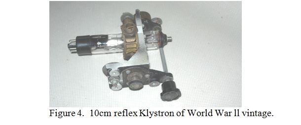
If a proportion of the output is fed back into the input, the device becomes an oscillator. However, keeping an electron beam of more than a few milliamps narrow and bunched within the drift space in the face of the mutual repulsion of the electrons defied attempts for many years to generate more than a few watts of power at centimetric wavelengths. A simple modification to the above device for use as an oscillator dispenses with the second rhumbatron and uses a reflecting plate held at a large negative voltage to act as an electrical mirror. This sends the now bunched electrons back through the rhumbatron towards the cathode. The electrons are eventually collected by the body of the rhumbatron after executing several cycles of oscillation through its gap. Such a device is called a “Reflex Klystron”, and an example of one used as a local oscillator in a 10cm airborne radar, together with the integrated mechanical tuning system for its rhumbatron is shown in figure 4.
Unfortunately, simple reflex and two cavity klystrons were only capable of a few watts output. The result was that klystrons failed to make a major impact on the remarkable microwave developments which occurred during World War ll except as laboratory sources of microwaves and as local oscillators in radar and communications equipment. Since that time intensive development has greatly improved the situation, and klystron amplifiers have found extensive application in terrestrial and satellite microwave links. This has largely been achieved by using several “dummy” cavities along the electron stream to maintain and improve the bunching, and a strong magnetic field coaxial with the electrons to confine them to a narrow stream. A variant on this theme is to replace the intermediate cavities by an extended wave-electron interaction system employing a carefully dimensioned spiral of wire to slow the wave to match the speed of the electrons. This is the basis of the “Travelling Wave Tube” amplifier. The result is that modern Multi Cavity Klystrons and Travelling Wave Tubes can produce kilowatts of mean RF power at centimetric wavelengths, although they are less successful at producing high peak power. In a future article I will describe another breakthrough in high power microwave generation; the Magnetron.
| Back |
|---|
PRAECEPTOR