AB INITIO
| Back |
|---|
It all started with the expansion of the railways in the early 1800s. For safety reasons and for the control of two way traffic on the lines, it was essential that signal men in their signal boxes, (who controlled both flag type signals and points), could communicate with others further down the line at a speed faster than a steam train or a horse could run. The optical telegraph was already well developed, but was really only suitable for use from hill top to hill top with line of sight between them. Railways, on the other hand, “don’t like hills”, and were built with very gradual inclines and, like canals, were routed around hills. However, early experiments with electricity had shown that, with this medium, cause and effect were almost instantaneous, and so developments proceeded with various forms of electric telegraph. Initially, several kinds of what to-day we would call “analogue systems” were tried. The best known of these was the “Cooke and Wheatstone Telegraph”, in which currents of various strengths, corresponding to various letters of the alphabet, were sent along five or six wires laid along side the track. At the receiving end, these wires were connected to five galvanometers mounted in a row on the font face of a cabinet. Electric currents in the various wires caused the galvanometer needles to point in turn to different letters of the alphabet which were marked on the face of the cabinet. This was only partially successful, (apart from it being rather slow), because, due to leakage, the current received was sometimes less than the current sent which led to errors. A better system, based on the binary rather than an analogue system, where the current only had to be “on” or “off”, was invented by Samuel Morse in the USA in 1837. Moreover, by using an “inker” at the receiving end, a permanent record was created in case there should be any dispute at a later date about what had been sent. Morse’s original code, although binary in essence, used a ‘two dot’ dash length, a ‘four dot’ dash length and several different spacings between dots and dashes. Not surprisingly, this produced copious errors, particularly when interfering signals from adjacent lines were present. However, within a few years Britain, the USA and much of Western Europe were criss-crossed with telegraph systems using copper wires supported on poles and all using various versions of the Morse Code, (Continental code, American code, etc.) Eventually, the “International Morse Code”, (the one in use today), evolved but it took several years to displace the older ones. Very soon, telegraph operators listening to the distinctive clicking of the inker learned to translate the sound into text more quickly than reading from the paper tape, and the inker and its tape were largely dispensed with.
Other methods of sending
While we are dismissing “non radio” use of Morse Code it should also be mentioned that Morse messages can be sent by several means other than radio. Under “line of sight” conditions, the use of an electric torch or an Aldus Lamp was common on airfields, and during and between the two World Wars, the Royal Navy used a “shuttered searchlight” for communicating between ships at sea. By using a mirror to reflect sunlight, (the heliograph), the British army in India and elsewhere during the 19th and early 20th Century achieved communication ranges of over 100 miles. During World War ll, messages were also sent by captured British aircrew between huts after “lock-up time” in German prisoner of war camps by tapping on the water pipes which ran throughout the camp. This communication and its widespread distribution system gave rise to the term “Grapevine”. Messages can also be sent by waving a flag in a particular manner, as distinct from semaphore.
Then came two important developments: Teletype machines for use on landlines, and spark transmitters, (initially with coherer receivers), for “wireless transmission”. Teletype systems used a binary code consisting of five symbols for each character plus ‘start’ and ‘stop’ signals. These were produced by a succession of five negative or positive voltages applied to the land line to represent each letter of the alphabet. These “Teleprinters” were often used for printing the paper tape stuck to hand delivered “Telegrams”. However, the development of land line teletype and its evolution into Radio Teletype, (RTTY), is another subject.
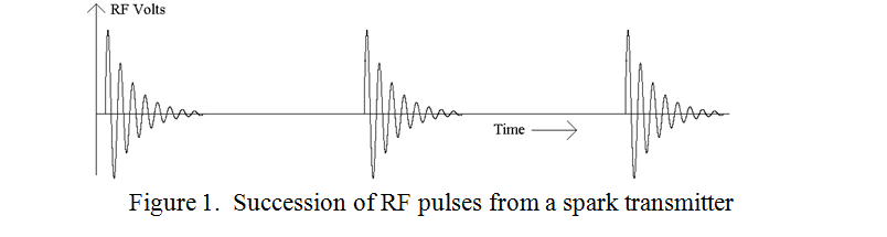
The discovery during the closing years of the Nineteenth Century that electrical sparks produced detectable effects at a distance launched the “whole new world” of “wireless” communication. The spark transmitter consisted of a Rhumkorff coil, or its smaller brother, the motor vehicle ignition coil. (These were becoming increasingly available around 1900 from the newly evolving motor trade). On its low voltage side, an electro-mechanical circuit breaker similar to that used in an electric bell, was used. This produced, on the high voltage side, a rapid succession of sparks between the spark electrodes, one of which was connected to an aerial wire and the other to earth. The result was the radiation of a succession of damped RF waves with a repetition rate of a few dozen up to a few hundred pulses per second as illustrated in figure 1.
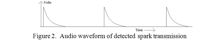
The receiver consisted of an aerial and earth similar to those of the transmitter, a coherer and its battery, and an inker with its paper tape. (The operation of coherers was discussed in an earlier article). In operation, the coherer in the receiver probably started to conduct on receipt of the first and largest RF pulse. If the coherer was of the “dry filings” type such as the Branly-Lodge type, it was then made to de-cohere by giving it a sharp tap, however, during its conduction phase it could pass sufficient DC current to operate the inker to mark the paper tape. If the coherer were of the mercury and oil type, such as the Lodge Muirhead or the Italian Navy type, it was self restoring and could be used with head phones. What would be heard was a succession of clicks corresponding to the succession of damped RF pulses. There might be anything between 30 and 400 of these clicks per second and so a tone with copious harmonics would be heard. The length of each click depended on the restorative properties of the oil film in that type of coherer which had been temporally punctured by the voltage across it. When rectifying detectors became available, using a “Carborundum detector”, a “crystal and cat’s whisker”, or later a thermionic diode, the shape of the rectified pulse and its harmonic content affected the sound of the note and this could be used by the operator in addition to the frequency of the audio pulses to distinguish a wanted from an unwanted transmission. Remember this was in the “Broad-Band” era, before tuned transmitters and receivers became available. An impression of the audio waveform resulting from the ‘detection by rectification’ and filtering of typical RF pulses is shown in figure 2.
The middle years
The development of the thermionic diode into a triode meant that amplification of both audio and RF signals could be achieved. Moreover, by feeding a little of the output of an amplifier back into its input, a sustained pure continuous RF signal could be produced with greater efficiency than by spark. However, this did not lead to the immediate redundancy of spark transmitters because the resulting pure CW signal could not be detected by any of the then current methods, i.e. any type of rectifier or coherer or a thermionic triode. The pure CW signal was silent! (CW signals should properly be called ‘Interrupted’ Continuous Wave signals because the information is carried in the interruptions in the form of dots and dashes). An additional process therefore had to be employed at the transmitter to render such signals readable. This process was to “modulate” the outgoing waveform at an audio frequency. Such transmissions were known as “Modulated CW”, (MCW), and are still in limited use to this day where AM receivers are the order of the day. (The main use today of MCW transmissions is by Airfield and Maritime navigational beacons).
The use of positive feedback in a valve amplifier was soon made use of to greatly increase both the sensitivity and selectivity of radio receivers, (by factors of about a thousand). However, by adjusting the feedback to be just “over critical”, i.e. with the feedback stage only just oscillating, the received ‘silent’ pure CW Morse signals could be heterodyned to produce an audible tone. The delicate adjustment of feedback was known as “reaction” and the receivers were known as “Straight receivers”. This was probably the commonest type of system in use during the 1920s and 30s. It is interesting to note that modern “Direct Conversion” receivers, as used in short range systems such as “key-fob receivers” often use this principle. Also, Direct Conversion receivers are often built by beginners for reception of CW and SSB transmissions, although these days they are built with transistors instead of valves.
Modern Times
A useful next step in receiver design was to make the tuneable feedback stage produce a heterodyne (or beat) frequency beyond the range of human hearing. This frequency, between the carrier frequency and audio frequencies, was known as the “intermediate frequency”, (IF). Having converted any incoming carrier frequency to this constant intermediate frequency it was much easier to perform most of the amplification and frequency filtering at the IF. A second oscillator, close in frequency to the intermediate frequency was then used to beat with the intermediate frequency making the pure CW signals audible. This second oscillator was known as the “Beat Frequency Oscillator”, (BFO), and the whole system became known as a “super heterodyne” system, (Superhet).
Radio amateurs have always been keen to extract information from the weakest signals and complete a QSO with distant or rare stations, even under difficult or noisy conditions. In this quest, modes other than Morse have been developed such as RTTY, AMTOR, PSK31, etc for live “chatty” contacts, and WSPR, WSJT, etc. for just recognising that some sort of signal has got through. However, Morse is still one of the better systems, although it has to be slowed down and read off a screen for really poor signal to noise conditions.
In 1948, the mathematician Claude Shannon derived a formula relating the maximum data rate that could theoretically be achieved in “bits per second per Hz of bandwidth” for a particular signal to noise ratio. This implied that there was no limit to how low below the noise a signal might be, it would always get through if one was prepared to slow the rate of transmission, narrow the bandwidth appropriately, and wait long enough. The inevitability of errors was accepted and so ‘error correcting codes’ were evolved. This in turn meant more characters had to be sent in a given time than just the intended data and this in turn implied a broader bandwidth. The relationship between the various factors is logarithmic and slightly complicated, but error correcting codes are used in all the more sophisticated systems. Error correcting codes are not usually sent with Morse transmissions, but when “extra slow Morse”, (QRSS), is displayed on a screen, visual integration and the human brain is remarkably adept at correcting text with wrong or missing characters, particularly when the text is more or less what is expected. This is what helps to make the intelligibility of very slow Morse almost comparable to the computer generated error correcting weak signal modes. Unfortunately, “slow” often means very very slow, making “dots” last up to 60 seconds and “dashes” three times longer.
| Back |
|---|
PRAECEPTOR