Some things can go faster than light, but not ‘material’ things. Three examples of these things are; the cutting point of scissors, the meeting point of lines as the lines go from crossing to parallel, and the phase of a wave. But these are imagined things, things in the mind. In the case of waves, it is the group of waves which carries information, and this can only travel slower than, or at the speed of light. In fact it can be shown that in a medium where the phase of a wave travels faster than light, the information or message contained in the waves travels slower than light such that the ‘phase velocity’ times the ‘group velocity’ is equal to the square of the velocity of light. So much for academia.
Refraction
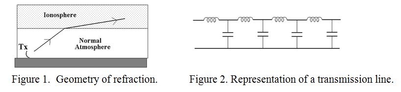
Figure 1 is a reminder of the situation, showing the relative geometry of the Earth, lower atmosphere and ionosphere. The ionosphere is just like the normal atmosphere except that some of its atoms have been split up into negative and positive ions by the ultra-violet rays from the sun.
I have looked in a couple of editions of the “Amateur Radio Handbook” for a good explanation of ionospheric refraction, but these were not of much help. These talked about the free electrons being caused to vibrate by the alternating electric field of the wave, thus generating a secondary set of waves which were 90 degrees in advance of the original wave. The resultant of combining the original and the locally generated wave, (they said), was therefore in advance of where it would have been. However, following through the process of electric field, acceleration of electrons, velocity of electrons, resultant magnetic field and resultant electric field, (by Maxwell), it is difficult to see convincingly the hoped for leap forward in the phase of the wave. In reality, the actual process is extremely complicated and a rigorous analysis involves resolving the wave into opposite hands of circular polarisation and then treating the ionosphere as a chiral medium.
Treatment by analogy
Much of the theory of electricity has to be thought about by analogy. For example, a well known analogy involves using water as an analogy for electric charge. ‘Voltage’ then becomes the pressure of water, (as shown by its head or height), ‘resistance’ by imagining a small diameter pipe, and even ‘Ohm’s Law’ is imagined as “the rate of water flow equals the pressure divided by the resistance”. It is often useful to use different analogies for different aspects of electrical phenomena. For example, imagining the electron as either a particle or a wave depending on whether one wishes to explain the photo-electric effect or electron diffraction patterns. Also, different people prefer different analogies. The following is mine which may appeal to some people.
Space has many similarities to a parallel wire transmission line, except that space allows the wave to spread out whereas a transmission line guides the wave in a particular direction. An ideal parallel wire transmission line allows the propagation of a pure “Transverse Electro-Magnetic Wave”, at the speed of light and is a good analogue in many ways. It has a wave impedance equal to the square root of (the inductance of the wire per unit length divided by the capacitance between the wires per unit length). Whereas space has an impedance of the square root of (the permeability of space (Henry per metre) divided by the permittivity of space, (Farad/m). In both cases, the speed of propagation is the reciprocal of the square root of (the products of the inductance and the capacitance per unit length). Thus they can both be represented by an equivalent transmission line as shown in figure 2. The volts or ‘E’ field can be regarded as the driving force causing current, (in the case of the transmission line), or Magnetic field, (in the case of space), to flow respectively. In the case of the transmission line, each series inductance slows the charging up of the next capacitor and only when this has some charge does it start charging up the next capacitor, and so on.
However, the Ionosphere is not totally ‘free space’ as it contains a weak plasma. I.e. it contains free electrons and positive ions due to ionisation by sun. A plasma is neutral overall, but if it is subjected to an electric field, the electrons are displaced one way and the positive ions the other. If now the E field is removed, the displacements of the ions is restored to the “unpolarised” state, but not before they have overshot a few time with gradually decreasing amplitude rather like the release of a displaced pendulum. The frequency of the oscillation of charges is determined principally by the ion density, and is known as the “Plasma Frequency”. For the thin air at an altitude of between 80km and about 500km, and under day-time solar radiation, this frequency is in the order of a few MHz.
The real situation
Free space, (at this altitude and ionised by the sun’s ultra-violet rays), thus contains potential resonators. If a radio transmission at the plasma frequency attempts to pass through this space, it is both absorbed and reflected as it would be by a conventional “L-C” tuned circuit, and like a tuned circuit, the medium looks inductive below and capacitive above the resonant frequency. Returning to the analogy of a transmission line, at a frequency lower than the plasma frequency, this is equivalent to the shunting the capacitors by inductors as indicated in figure 3.
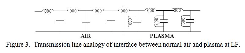
At the resonant frequency of the shunt ‘L’ and ‘C’ the result of the transmitted wave being absorbed and scattered is that some of it is reflected back towards the transmitter. In “radio parlance” the plasma frequency is known as the “Critical frequency” and it can reflect waves sent vertically upwards from the transmitter. (These are called Near Vertical Incidence Sky waves). If the transmitted frequency is below the plasma frequency, the resultant shunt inductance makes the shunt capacitors look “less capacitive”, increasing the velocity of propagation, (beyond the speed of light), allowing the waves to be gradually bent back to earth. If the transmitted frequency is higher than the plasma frequency, the shunt inductor-capacitor combination looks capacitive, slowing the speed of propagation, thus bending the refracted ray away from the normal and out into space.