| Back |
|---|
So called “Standing Waves” occur whenever two waves of the same frequency travelling in the same medium travel in opposite directions. In radio science, this medium is usually a transmission line, (for example from a transmitter to an aerial). The wave travelling in the opposite direction is usually the result of the aerial not radiating all the transmitter power sent to it and consequently reflecting some of it back towards the transmitter. This reflection and the consequent standing wave has three disadvantages: Firstly not all of the power sent to the aerial is radiated; Secondly the actual power sent may be reduced as the transmitter may have internal protection which automatically reduces its output power when it detects a mismatched load; and Thirdly the transmission line between the transmitter and the aerial will have increased loss over that normally measured due solely to the standing waves.
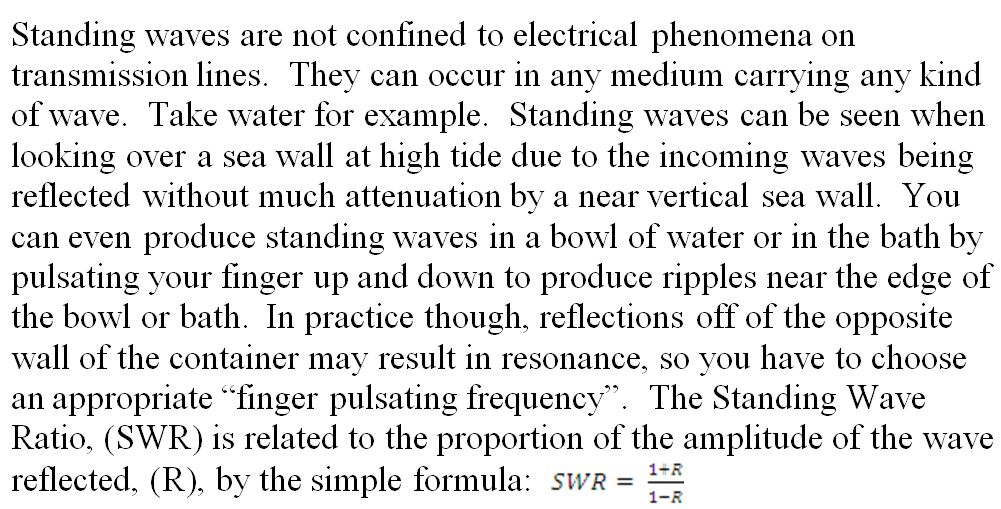
What do standing waves look like? They are not stationary in the amplitude direction. In the case of water, the water goes up and down at the frequency of their source. That is, at their peaks, the instantaneous water height goes up and down at their frequency of arrival. Although the water height goes between its maximum “up” and its maximum “down”, the region between the maxima and minima stays calm at the average level.
Back to standing waves on transmission lines. One of the measures which amateurs use to assess the “goodness” of their aerial is the standing wave ratio on the transmission line feeding it. What they actually measure with most standing wave indicators is not the standing waves, but usually the reflected signal from the aerial, which is then displayed as the equivalent Standing Wave Ratio on the line. I say “usually” because at the higher frequencies or shorter wavelengths there are instruments which actually display the maxima and minima of voltage on the line. Historically this was done using a transmission line comprising two parallel bare wires. This was known as a “Lecher line” after its inventor Ernst Lecher. He used it to measure the wavelength of his spark transmitter by placing a small lamp bulb across the pair of wires, or a neon bulb close to the wires, (to detect the voltage maxima). The distance between adjacent maxima, (or adjacent minima) gave the half-wavelength of his oscillations. The same technique is still in use at short wavelengths, e.g. microwaves, using a rigid coaxial line or a rectangular metal waveguide with a narrow longitudinal slot in it through which a small probe is inserted. The probe is connected to an RF Voltmeter and moved along the slot to determine the maxima and minima of the standing wave. The same technique was used to measure the wavelength of the first experimental cavity magnetron in 1940. The Standing Wave Ratio, (SWR), is just the ratio of the maximum amplitude to the minimum amplitude as for example, 1 to 1, (for a perfect match of the load to the transmission line) or 1 to 5, (a rather poor match). The SWR is often abbreviated to ‘S’, leaving out the words “1 to”, as in S = 1 or S = 5.
The shape of a standing wave is not that of a sine wave except for very small standing wave ratios, i.e. for a near perfect match corresponding to very low reflection from the far end of the line. For modest values of SWR, the wave shape is that of distorted sine waves. At the extreme, for a unity reflection coefficient, where S becomes infinity, (produced by a short or open circuit at the far end of the line), the wave shape becomes that of a rectified sine wave. Examples of the shape of four standing waves with standing wave ratios, ‘S’ of 1, 2, 5, and infinity are shown in figure 1.
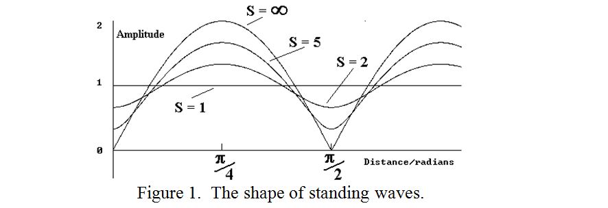
It is seen that for unity reflection coefficient, the minima fall to zero. At these points complete destructive interference between the forward and backward wave occurs over an extremely narrow region. As the minima are much better defined than the maxima, the exact distance between minima is usually used to accurately determine the half wavelength.
All transmission lines have some loss. Most of it is due to “Ohmic Loss” in the conductors. Therefore the higher the characteristic impedance of the transmission line, the smaller will be the proportion of Ohmic Loss and therefore the lower will be the loss for any given length. Unfortunately, the input impedance at the centre of a dipole is only about 72?? and most transmitters are designed to work into a similarly low impedance of 50?. Although a dipole can be connected directly to a transmitter with an acceptable mismatch ratio of about 1.5 to 1, a transmission line of such low impedance of 50 or 72? cannot be constructed of parallel wires. (The conductors would have to be nearly as thick as their spacing). Fortunately, conveniently sized coaxial cable has a characteristic impedance of the right order, (50 to 72? ), to produce an acceptable match to a dipole, and is commonly used. However, ‘coax’ has a rather higher loss per unit length than that of parallel wire lines, (typically a dB or two per hundred metres at 30MHz even for the very best varieties). Moreover, the stated loss for coax is measured when working with a matched load at its far end. The presence of standing waves on any sort of transmission line can increase the actual loss several fold. This is because transmission loss is proportional to the square of the current for conductor loss and to the square of the voltage for dielectric loss. For conductor loss, the increased loss at the current maxima is therefore not compensated for by the decreased loss at the minima. This results in more loss than that published by the coax manufacturers. Calculation of this excess loss due to standing waves is difficult and involved and depends, among other things, on the line length and whether there are more current maxima than minima on the line. Charts showing this “excess loss” in some radio books are less than exact.
The usual way of matching the aerial to the transmission line is with an “Aerial Tuning Unit”, (ATU), sometimes called an Aerial Matching Unit. However, this should preferably be placed at the aerial end of the transmission 1ine to reduce standing waves on the feeder if excess feeder loss is to be avoided. Placing it at the transmitter end may be more convenient for “hands on” tuning and may produce a perfect match for the transmitter to work into, but it does nothing to eliminate excess feeder loss
| Back |
|---|
PRAECEPTOR