| Back |
|---|
Many scientists have doubted whether Marconi could really have heard a signal from across the Atlantic using such primitive, insensitive and unselective apparatus with an aerial system dictating a fundamental wavelength of approximately 360 meters. I personally think he did receive a signal with the following slightly tentative, “order of magnitude” reasoning, although I concede that he was fairly lucky.
It is not uncommon these days, under good conditions, to hear North American and Canadian stations on 20 meters and occasionally on 40 meters coming in at strength 9 when only running 100 Watts. If we equate signal strength “S1” of an AM signal to 1 microvolt at the receiver input with a nominal impedance of 50Ω, and 6 dB per “S” point, then S9 equates to 256 micro volts across 50Ω Now a coherer has an almost infinite impedance in its pre-breakdown state, so for maximum sensitivity it should be placed at the end a half wave or multiple half wave aerial. The end point impedance of such is usually taken to be about 5000Ω which gives a voltage at the end of the wire of 2½ milli Volts for an S 9 signal. If we assume that his “Italian Navy Coherer” was ten times as sensitive as the earliest sort of the kind that I made, and described earlier, (in Part ll), then it might have detected a peak RF signal in the order of 1 Volt. Now if Marconi’s transmitter aerial system can be regarded as a quarter wave antenna tuned against a good ground, then its radiation resistance at the fundamental wavelength would be 36 Ohms, (with a “Q” of about 10). If his transmitter induction coil charged up his aerial system to +100 kV just prior to the spark gap breaking down, and if the break down can be considered as an instantaneous shorting to earth, then the initial current flowing is not infinite but is limited by the radiation resistance to 100 kV/36Ω = about 3000 Amps. The stored magnetic energy generated by this current results in current continuing to flow even when the voltage has reached zero resulting in the aerial system peak voltage reaching -90 kV during the next half cycle and so on., but this is irrelevant. It is only the first “Giant Pulse” which matters to coherers, and Marconi’s totally untuned systems would have preserved the sharp leading edge of this pulse. The near instantaneous break down of the spark gap results in the generation of harmonics of the fundamental. The 10th harmonic, (about the optimum wavelength for crossing the Atlantic), would have about 10% of this initial current surge, say 300 Amps.
Compare this with a modern 100 Watt transceiver. This produces about 1.4 Amps RMS into 50Ω or 1.7 Amps into 36Ω and can, (under good conditions), produce a transatlantic signal of 2½ milliVolts on the end of a half wavelength wire, so a transmitter aerial current of 300 Amps should produce a voltage of 2½ × 300/1.7 = 440 milli volts, which is of the order of magnitude which can be detected by the most sensitive of coherers. It is entirely possible that his transmitter aerial was better than 10% efficient at extracting the 10th harmonic from the spark. After all, Hertz used spark gaps to generate sub-metric waves.
As a matter of interest, I have recently built a very adaptable crystal set and measured some voltages and currents which can be obtained in the St Albans area. By adaptable, I mean that I can tap the aerial, tuning capacitor and crystal almost anywhere on the tuning coil as well as being able to either series or parallel tune it. The best results were achieved when receiving “Radio 5 live” on 909 kHz using series tuning with maximum inductance and maximum capacitance in series, when the voltage on modulation peaks across the unloaded inductance reached 80 Volts peak to peak. This high “open circuit” voltage collapsed of course when any current was drawn. The detected voltage, using a “small signal” germanium crystal, (the sort where you can see the cat’s whisker through the glass), was 3.3 Volts when 0.7 mA was drawn, and was sufficient to power the HF and reaction stages of a simple straight receiver, but more of this anon. A photograph of the crystal set is shown in figure 1 and the circuit diagram is shown in figure 2.
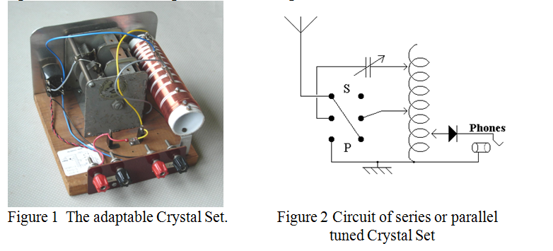
Circuit diagrams of crystal sets often show an RF bypass capacitor across the audio output, but I found that this made no difference to the loudness of the received signal, or to the selectivity, whether head phones or a small cabinet loudspeaker were used via a suitable matching transformer. The signal strength from “Radio 5 Live” was quite adequate for comfortable listening by loud speaker at a distance of about 3 feet.
The peak voltage achieved by the induction coil in Marconi’s successful Trans Atlantic test of December 1901 was not recorded, but the mean power input was 12 kW and the effective length of his antenna was 180 metres. The scientists, who had predicted that it should not be possible to cross the Atlantic with Hertzian waves, had based their calculations on diffraction theory over a smoothly curved earth, but we now know that this is not the whole story.
In 1902 the American electrical engineer Arthur Edwin Kennelly and the British physicist and electrician Oliver Heaviside, independently and almost simultaneously, announced the probable existence of a layer of ionised gas high in the atmosphere that affects the propagation of radio waves. This layer, formerly called the Heaviside or the Kennelly-Heaviside layer is now known as the F2 layer and is only one of several layers.
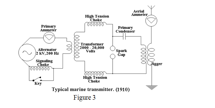
By 1910 all Marconi’s marine transmitters had some form of elementary tuning and were usually powered by an alternator generating a few hundred Hertz at a couple of kV. A typical circuit diagram is shown in figure 3 below.
| Back |
|---|
John G0NVZ