AB INITIO
| Back |
|---|
Linear polarisation is usually thought of as an electromagnetic wave with the electric field staying constantly in one direction, (Vertical for vertical polarisation). The magnetic field however stays at right angles to the electric field, and is horizontal for vertical polarisation. Both stay at right angles to the direction of propagation. Circular polarisation can be thought of as the electric field, (as might be seen from a point on the route of the propagating wave), rotating as it travels past the observer with the magnetic field being at right angles to it and rotating with it. The electric field is often represented as a series of arrows, (called vectors), whose length is representative of the field strength. If the rotating electric field of the circularly polarised wave could be frozen in space and time, (which of course in reality it can’t), then the electric field would look something like a “corkscrew” as shown in figure 1. In this figure, imagine that you are standing behind the transmitter, (the suitably phased crossed dipoles in the figure, producing the rotating electric field), and looking out in the direction of propagation.
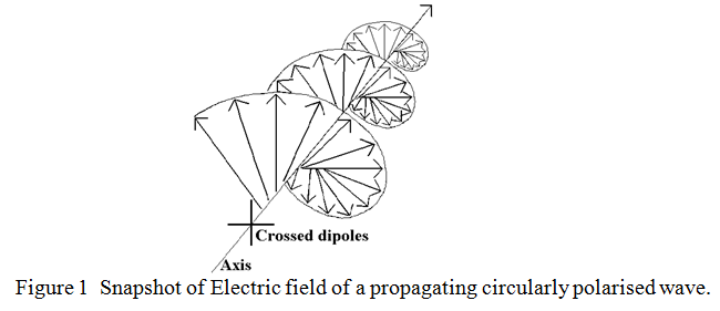
Actually, the wave does not corkscrew its way through space, but it travels as a rigid corkscrew at the speed of light. It’s a bit like pushing the corkscrew into a cork without rotating it. Figure 1 shows a normal right handed corkscrew, and if the “frozen” wave looks like this, it is said to be Right Hand Circularly Polarised. It is perfectly possible to have a left handed corkscrew which you would have to rotate the other way to get it into a cork. If the “frozen” wave looked like that it would be said to be Left Hand Circularly Polarised. An aerial designed to transmit Right Hand Circular polarisation cannot receive left hand circular polarisation and vice-versa, in the same way that a vertical aerial cannot receive horizontal polarisation. Defining which hand of circular polarisation an aerial transmits and receives causes much confusion. The most notable case of confusion was during the initial broadcast of television pictures across the Atlantic via the “Early Bird” satellite in the mid 1960s, when the French received excellent pictures from America but the BBC got only poor pictures from the same satellite. It all depended on how one defined left or right handed. It’s like asking the question, “which way do the hands go round on the church clock?” The parishioner looking up at the clock face sees the little hand go from 12 to 1, but the clock winder, who sets the time from inside the clock tower sees the hands go the other way round. For circular polarisation, it all depends on whether you are sending or receiving. It has now been internationally defined as “From the sender’s point of view”.
Another way of looking at circular polarisation is to resolve it into Vertical and Horizontal components. We then find that it consists of two identical components but with a phase shift of 90 degrees between them. Whether the phase shift is “advancing” or “retarding” determines which hand is produced. For those not familiar with “resolving”, take observing the pedals of an exercise bike as an example. We all know that the pedals go round in a circle. But observed from the front or rear of the cyclist, the pedals appear to go up and down in simple harmonic motion, i.e. as a sine wave. Observed from above the pedals seem to move from front to rear, also as a sine wave, but phase shifted by a quarter of a cycle from the front or rear view. When circular polarisation is resolved into its horizontal and vertical component sine waves, these look like those of figure 2.
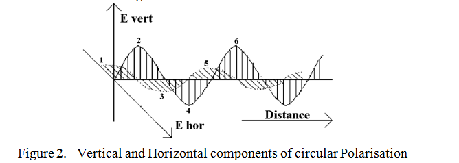
We can see that the two components in the figure form a right handed corkscrew by following the numbered peaks labelled 1, 2, 3, 4, etc. The peaks of one component correspond to the zeros of the other.
Aerials
There are two main types of circularly polarised aerial: the first of which is designed to transmit and receive one hand only, and the second, a more flexible type, is designed to transmit or receive either hand with the flick of a switch or both hands of polarisation simultaneously with different output sockets. The first type often consists of a spiral of wire forming a Helix, wound in the same direction as the circular polarisation which it is desired to transmit or receive. This is placed in front of an Earth plane. A typical structure is shown in figure 3.
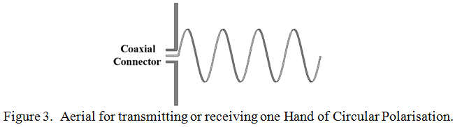
The gauge of the wire in this type of aerial is not particularly important, but the pitch and diameter of the helix should be such that the circumferential distance along the wire between one turn and the next is about 1¼ wavelengths and the pitch, (i.e. the spacing between turns), is ¼ of a wavelength. The action may be compared to an end-fire array in which all the elements are driven. The ground plane, (acting as a reflector), should be at least ½ a wavelength square. This configuration will produce near perfect circular polarisation over a moderate bandwidth if the number of turns in the helix exceeds about half a dozen The input impedance of such designs is usually about 140 Ω This type of helically wound aerial should not be confused with the helically wound “short dipole”, or “short monopole above a ground plane”, (sometimes known as a “rubber duck”), in which both the pitch and the circumferential distance between turns is very much less than a wavelength. Short dipoles and monopoles radiate in what is known as the “normal” or “radial” mode, whereas helically wound circular polarised aerials radiate in an “axial” mode.
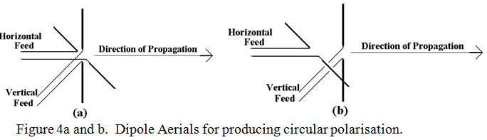
Another type of aerial where the polarisation is fixed by the structure makes use of much of the discussion in the above recap, but in this case to synthesise, (rather than resolve), circular polarisation from two linearly polarised waves produced by dipoles at right angles. If the dipoles are in the same plane, they need to be fed from a “Y” junction with a ¼ of a wavelength extra length in one arm of the ‘Y’. Which arm has the extra length in it determines which hand is transmitted or received. However, if the crossed dipoles are staggered in the direction of propagation by ¼ of a wavelength, they can be fed exactly in phase to produce circular polarisation. These two situations are depicted in figures 4a and b.
Such aerials may have crossed reflectors and directors associated with them to concentrate or narrow the radiated beam.
By having control of the relative phase between the vertical and horizontal input and output feeders of the aerials shown in figure 4a, and 4b, either left or right hand circular polarisation may be produced and received. Also, both left and right hand polarisation together, but independently carrying different information on the same frequency may be produced.
| Back |
|---|