| Back |
|---|
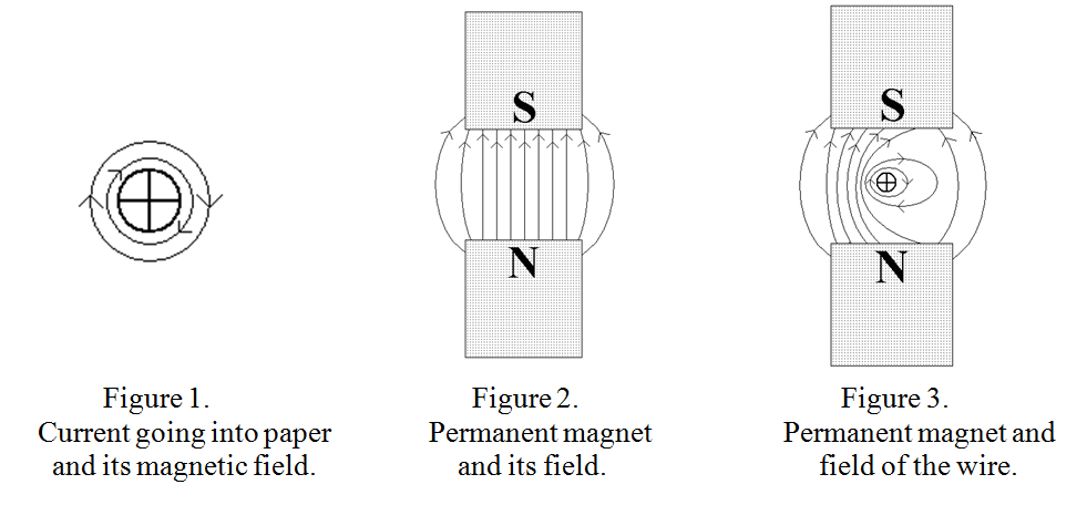
When dealing with electric current passing through wires in a magnetic field, (as in electric motors, dynamos and transformers), people often get confused, as mentioned above, as to which way the wire moves or armature turns, or which end of the wire becomes positive and which negative in the case of a dynamo or transformer. The usual rules for determining these things are “Fleming’s left hand and right hand rules”, using the thuMb, First and seCond fingers of the appropriate hand standing for Mechanical force, magnetic Field and Current respectively. But remembering which hand applies to a particular case is difficult and prone to error. However, a quick sketch of field lines provides a certain and quick-fire answer in all cases. The only thing to be remembered is Maxwell’s Cork-screw rule. That is: that when current is flowing away from you or into the paper, the magnetic field generated by it goes round the wire in a clockwise direction like a cork-screw being driven into a cork. This is illustrated in figure 1 where the vertical cross, (like the “rear view of an arrow”), is conventionally used for something going away from you.
Motor case
If the wire carrying a current, (say into the paper), is placed in a magnetic field, (say produced by a permanent magnet, as shown with magnetic field lines in figure 2), then the field of the wire adds to that of the permanent magnet on the left hand side and subtracts and therefore reduces the field on the right hand side. This is shown in figure 3, where the close spaced lines indicate the stronger magnetic field and the wider spaces lines indicate the weaker field. If the field lines are regarded as “springy” and trying to get away from each other it is clear that the force on the wire and its movement, (if allowed), will be to the right.
Dynamo case
Similarly, in the dynamo case, if a wire not carrying current, but in the above magnetic field is moved to the right, the question is: “which end becomes positive and which negative?” This is governed by Lenz’s Law which states: “Whenever any change produces an induced current, the direction of current flow is such as to produce effects opposing the change”. This implies that if a current into the paper, (as in figure 3), causes the wire to move to the right, then moving the wire to the right tends to cause an emf in the opposite direction, ie, out of the paper. So the near end of the wire becomes positive and the far end, negative. (Current is always assumed to be a movement of positive charges, not electrons).
Transformer case
This involves no physical motion but involves a wire in a changing magnetic field. In this case, the concept of field lines, or lines of force is particularly valuable. Emf is only generated, or current induced to flow, if the net number of lines of force “linked to the wire” is changed or lines crossed. It is as important to know when an emf is not generated and a current is not induced to flow, as when it is. For example, if a wire not carrying a current is placed symmetrically in a uniform magnetic field, (similar to the positions shown in figure 3), and the magnetic field is increased, then no emf is generated. The number of lines of force on both sides of the wire is increased but no lines cross the wire and there is no change to the linkage of magnetic lines of force to the wire. Another way of looking at this is that the emf generated “out of the paper” by the increasing magnetic field to the left of the wire is equalled by the emf generated “into the paper” by the increasing magnetic field to the right of the wire. The relevant magnetic field must “link”, or encircle the wire to be effective. Linking or encircling most obviously occurs when the wire forms a loop, where magnetic field can pass through the centre of the loop or coil one way and return outside the loop the other way. This is illustrated in figure 4, where the magnet has been drawn as an electro-magnet so that its field may be varied without movement of either it or the coil with which the magnetic field is linked.
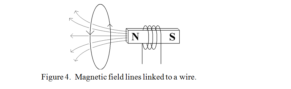
Increasing the power of the magnet by increasing the current through the coil does not alter the overall pattern of the magnetic field but it does increase the number of “North” field lines through the coil. Remembering Lenz’s Law, a current must try to flow in a direction such that its magnetic field opposes the increasing magnetic field from the magnet, hence, for an increasing magnetic “North” field, current will tend to flow in the direction indicated by the arrows on the wire.
The use of imagined Field Lines thus provides a fool-proof way of getting the polarity right, instead of having to rely on remembering whether it is Fleming’s left or right hand rule which has to be applied in a particular circumstance.
| Back |
|---|
PRAECEPTOR