AB INITIO
Back
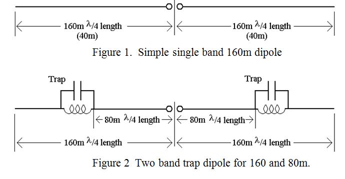
The term “trap” when applied to antennas is short and convenient but not entirely appropriate. Unlike an animal trap, it does not catch anything, but it does selectively “block” the path of the antenna current at a specific frequency. Let me explain. The radiating element of many antenna systems is a half wave dipole. (Although it’s always referred to as a half wave dipole, it actually needs to be a few percent shorter than half a wavelength for resonance due to “end effects”). That is fine for the frequency at which the radiating element is approximately a half wavelength long as it presents, at its centre, an impedance which is usually within a factor of 2 or 3 of the characteristic impedance of typical coaxial cable, (about 50 Ohms). (Reflectors and directors can change the feed point impedance by these factors depending on their length and spacing). Such factors are manageable using various matching devices and/or a balun, but factors much larger than these are not manageable. For example, a centre fed 160m dipole well clear of the ground has a feed point impedance of about 72 Ohms resistive. However, if the same aerial is fed with RF power at a harmonic of 160m, at say 80, 40, 20 or 10 metres, it looks like two end fed half wave dipoles at 80metres, and 4, 8 or 16 end fed multiple half wave antennas respectively at the higher frequencies. The dipole(s), at these higher frequencies, being end fed, presents an input impedance requiring a high voltage and virtually zero current: i.e. they present a very high input impedance, a couple of orders of magnitude greater than 50 or 72 Ohms. What is required to also obtain a good match at one of the higher frequencies, is a means of disconnecting the unwanted outer lengths of the aerial at these higher frequencies. This would ensure that only the length of wire appropriate to the frequency, (i.e. a quarter wavelength either side of the central feed point), is connected to the feeder. This is the function which the traps perform and they do it by behaving as simple “band stop filters” each tuned to a specific higher frequency. A band stop filter offers an extremely high impedance to the frequency to which it is tuned, but a low impedance to all other frequencies. They are used in pairs, one on either side of the central feed point, and at the same appropriate distance from it. They usually take the form of a parallel resonant circuit comprising an inductor and a capacitor in parallel sealed in a weather proof tube. A representation of a single band 160m dipole is shown in figure 1, and a “two band trap dipole” for 160 and 80 metres is shown diagrammatically in figure 2.
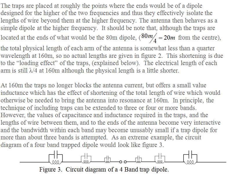
Each trap further from the central feeder rejects or stops a progressively lower frequency and therefore has progressively larger values of inductance and capacitance.
PRAECEPTOR
| Back |
|---|