| Back |
|---|
The aerial socket of most transceivers is usually mounted on the back, and the transceiver is often pushed to the back on the desk or shelf up against a wall. Then a thickish low loss coax to the Aerial is used and this often needs a right angle connector on the back of the transceiver. The sniffer box described performs the right angle task and also takes a sample of the coax voltage.
The Theory
The sniffer box consists in essence of a short coaxial section with an uninterupted central conductor to which is connected a very small capacitor feeding a sample of the RF power passing through the box to an output connector. The value of the coupling capacitor is not very critical and depends to a large extent on the capacitance of the coax feeding the ’scope, as the two form a capacitive potentiometer. For example, if the coupling capacitance is 2pF and the capacitance of the scope lead is 200pF, then the sample voltage fed to the scope is one hundredth of the transceiver output voltage. (The ’scope input impedance is usually so high that its effect can be neglected). A transceiver output power of 100 Watts into 50 Ohms gives 71 Volts RMS. Hence, 0.7 Volts RMS, or 2 Volts peak to peak will be delivered to the ’scope, which is a convenient level. (If you haven’t got a low value of capacitor of a few pF, then you can wind a few turns of insulated wire around the main conductor). The power consumed from the transceiver by the “Sniffer Box” and ’scope is absolutely negligible, as capacitive potentiometers consume no power and most ’scopes have an input impedance of at least one Megohm. (In the above example, the power consumed by the ’scope is half a microwatt). A nice feature of using a capacitive potentiometer feeding virtually an open circuit is that the amplitude of the ’scope display is almost independent of frequency, from 1.81 MHz to 29.7 MHz. The measured variation between these extreem frequencies is less than 1.5 to 1.
Construction
The device consists of a rigid metal box on which is mounted a SO239 socket, a PL259 plug and another miniature socket, (in my case a “Conhex” socket). The centre pins of the 239 and 259 are connected by a short length of wire, which has soldered to it a very small capacitor which also connects to the Conhex “sample output” socket feeding the ’scope via a length of miniature coax. The arrangement is shown in the photographs below.
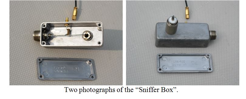
The PL259 free plug is mounted on the bottom of the box and the SO239 chassis mounting socket is mounted on the end as shown in photo. The socket is made for mounting on a metal box and presents no difficulty, but the plug is not and some inginuety must be used. PL259 plugs are usually sold with an optional screw-in insert for use with small gauge coax, and this insert is used to secure the plug to the bottom of the box. The size of hole in the box is fairly critical as the insert has a fairly small “lip” which must not go throught the hole. I found enlarging the initial ¼ inch hole using a round file with frequent tests with the insert to be satisfactory. As long as the box material is not too thick there should be several screw turns available on the insert. It is worthwhile making or adapting a spring washer to fit under the insert lip to prevent eventual loosening. Also it is difficult to tighten the insert inside the box, particularly when the central wire has been soldered in position. Therefore it is worth cutting a couple of saw grooves for a screwdriver in the lip as shown in the photo.
The impedance inside the box is not matched to 50 Ohms, but as the length of the box is less than 1% of the wavelength, even at 29.7MHz, this doesn’t have much effect. If you want to be really pedantic about 50 throughout you could bring an earth plane made of copper foil to within a mm or so of the central wire.
In the absence of a ’scope or even an ATU, the sniffer box could be used to feed a diode and a sensitive volt or micro-amp meter. The simple device described safely takes a small sample of the transmitted power for display, while avoiding exposing high levels of RF in the shack.
John, G0NVZ
| Back |
|---|