| Back |
|---|
Continued
Last month we saw that a balun should be used to connect between an unbalanced line, such as coax, (which usually has its outer braid earthed), and a balanced load, (such as a well placed dipole). Its purpose was to ensure that the two connections to the balanced load were fed equally and in anti-phase so that all the RF power was fed to the aerial and there was no power left over to travel back along the outside of the coax. We also saw that there were two kinds of balun called Current and Voltage baluns also called Choke and Transformer baluns respectively. The choke or current balun was relatively simple, just rejecting any “common mode” current, but was not capable of transforming its input impedance to that of the load. However, the voltage or transformer balun could transform the impedance ratio within limits, but had some disadvantages when covering a wide range of frequencies due to “leakage inductance” and incomplete isolation between the input and output windings. Most of these disadvantages could be overcome by using a third winding, “trifilar” wound, and using the windings as an “auto-transformer” as shown again, (for a 1:1 impedance ratio balun), in figure 1 below. Moreover, by altering the number of turns on the three different winding sections, different impedance ratios between input and output could be achieved.
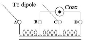
Figure 1 Trifilar wound 1:1 auto-transformer.
In an auto-transformer, some of the primary and secondary windings are shared, thus ensuring the tightest possible coupling between those windings which are in common. In the figure it can be seen that two coils are connected to the coax and two similar coils are connected to the aerial, so the transfer impedance ratio of this configuration is 1:1.
Detailed explanation
Using the transformer terminal designations A to D shown in figure 1, if the instantaneous voltage on the inner of the coax, D is +V relative to earth, B, then the voltage at C is +½V and the voltage at A is –½V. I.e. the output voltages to the aerial are symmetrical relative to earth. Also, both the coax inner, (or live), and the outer sheath, (earth), are isolated by one winding each of high inductance from the aerial connections, so this configuration is a true 1:1 transformer balun. An interesting feature of this circuit is that, theoretically, in a perfect system with a truly balanced output load, and where a 1:1 impedance transformation is sufficient, the current in the centre coil resulting from the input, is equal and opposite to the current resulting from the output. Ie no current flows in the centre coil. This only carries a small “error current” if the “balanced output” is not truly balanced.
Practical use can be made of this fact to improve the performance of the simple choke 1:1 balun discussed in Part1, fig. 1, by connecting a thin wire, tightly coupled to the outside of the coax, as a centre coil as shown in fig 2. This transforms the balun into a trifilar wound transformer without the electrical discontinuities caused by breaking the coax and connecting it to wire coils.
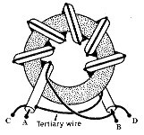
Figure 2 Toroidal trifilar wound balun using coax plus a tertiary wire.
If the load is truly balanced, the opposing currents in the main windings result in no magnetic flux in the core. Any unbalance causes only the “difference”, or “residual” current to give rise to flux in the core, as is the case for the simple choke balun. The relatively low current in this middle coil means that thin wire in close proximity to the coax can be used, ensuring tight coupling. In the ideal case of a truly balanced load, the RF power is confined to the much more sturdy coax than the thin wire. This technique is less applicable to higher impedance ratios than 1:1.
It may be difficult to visualise the directions of the induced currents in figure 2, so the input and output terminals have been labelled A to D to correspond to those in figure 1
Staying with figures 1 and 2, note that if the unbalanced input from the coax had been connected between terminals B and C rather than B and D, and the balanced output to the aerial had been taken from terminals A and D, a 9:1 impedance ratio device would have resulted. Unfortunately, in this case, the coil connected to the low impedance coax and therefore carrying the highest current would now be connected to the thin wire winding which is not good from the loss point of view.
A 4:1 Impedance Ratio Transformer Balun
This makes use of the 1:1 transformer configuration of figure 1 but with the windings connected as an auto-transformer as shown in figure 3.
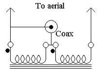
Figure 3. 4:1 impedance ratio Auto-transformer balun.
The operation is as follows: If the centre conductor of the coax has an instantaneous voltage “+V” relative to earth, (which it sends to the left hand arm of a dipole), then an equal and opposite voltage, “‑V” is induced in the right hand end of the right hand coil which it sends to the right hand arm of the dipole. The voltage between the feed points of the two arms of the dipole is thus 2V. As in all transformers, twice the voltage implies half the current, so the output impedance to the aerial of this Balun is four times that of the input impedance from the coax. However, it suffers from incomplete isolation of the aerial from the coax. There appears to be no perfect solution to designing the perfect balun for impedance ratios other than 1:1, (ie providing both voltage and current balance together with complete isolation), except to use both voltage and current baluns is series.
PRAECEPTOR
| BACK |
|---|
| Wire Baluns (Part 1) |