The VARC Lockdown Challenge was to make a 6m antenna from materials found at the home QTH. No sneaking off to local suppliers or mail ordering! A rummage through my garage found the following:
Plastic rectangular-section conduit, two telescopic Band 1 TV antennas, SO239 socket, ‘U’ bolts and miscellaneous bits of wood. Unfortunately, no useful lengths of aluminium rod or tubing.
‘Back of envelope’ calculations showed the feasibility of making a 50MHz (and perhaps also a 70MHz) dipole. Not particularly high-tech but hopefully a lightweight, portable, antenna might be a possibility.
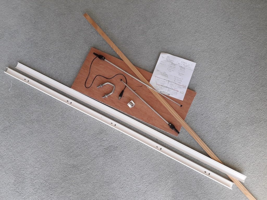
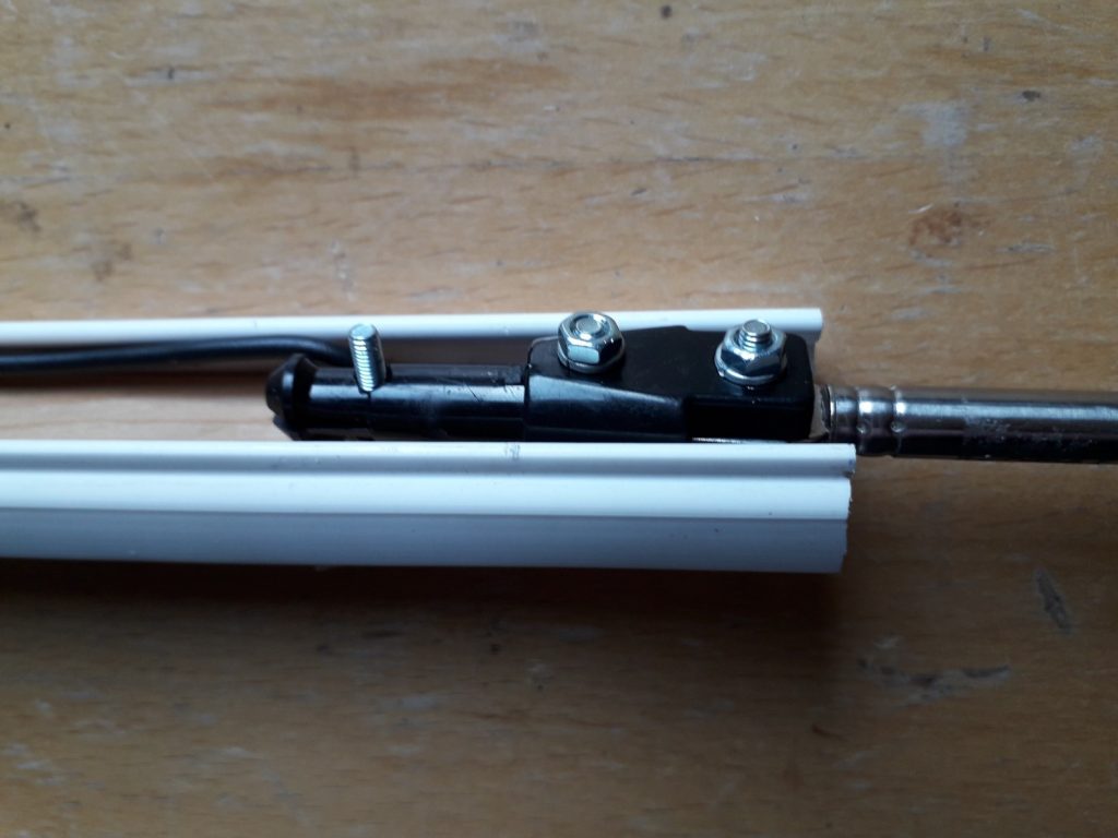
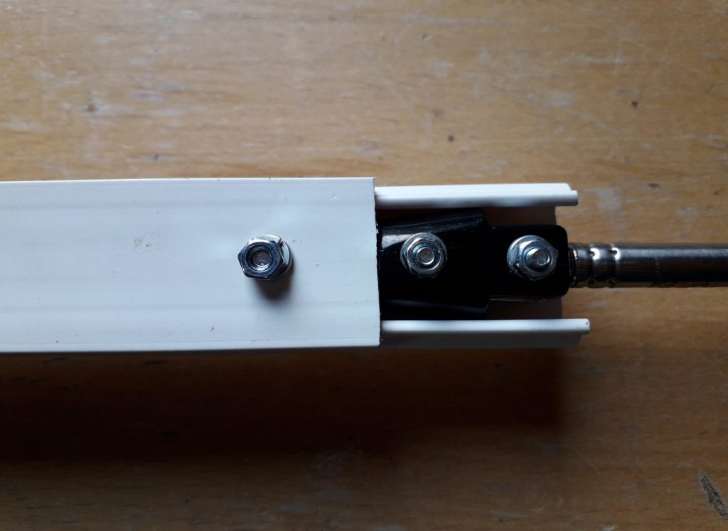
Work began by strengthening the plastic conduit, by gluing-in a wooden insert. Next, the antenna end fixings were drilled-out, rewired and reassembled.
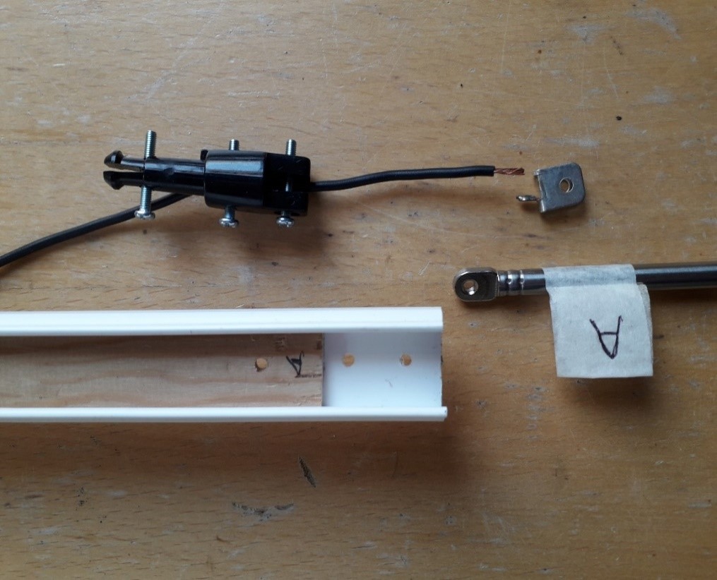
Nuts, washers & bolts were used to attach the telescopic antennas to each end of the plastic conduit (ends A & B).
A centrally located SO239 socket was wired to the telescopic antennas. Glue was applied to connecting wires inside the plastic conduit, to form a rigid structure, and so reduce the possibility of random resonances.
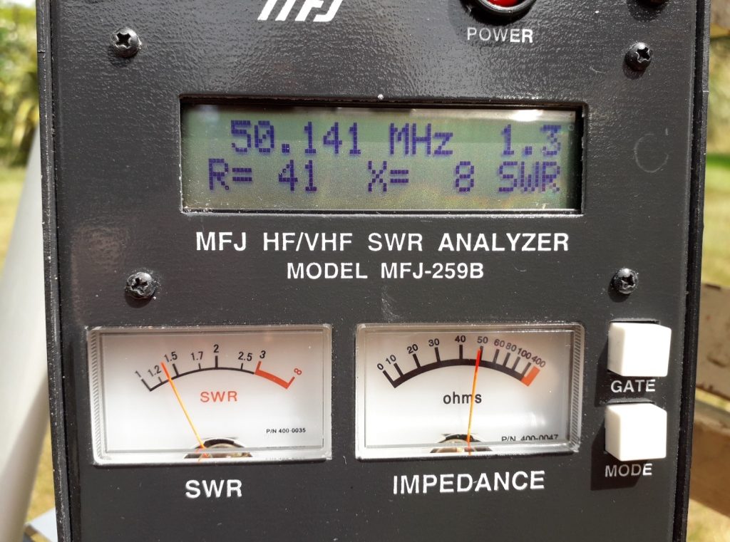
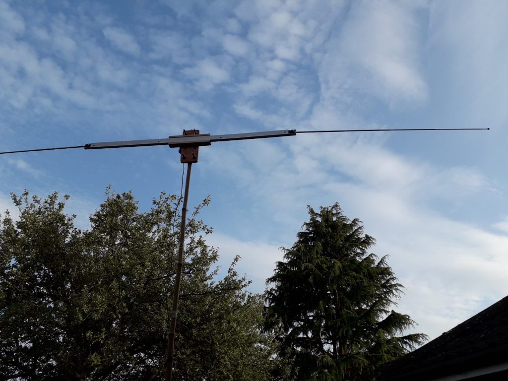
The antenna was adjusted for a calculated resonance of 50.150MHz (SSB centre activity frequency) and supported on a wooden step ladder at a height of 1.5 metres (0.25 wavelength) above ground. Although not an ideal height it was thought important to carry out some resonance/ confidence tests, before proceeding with further construction.
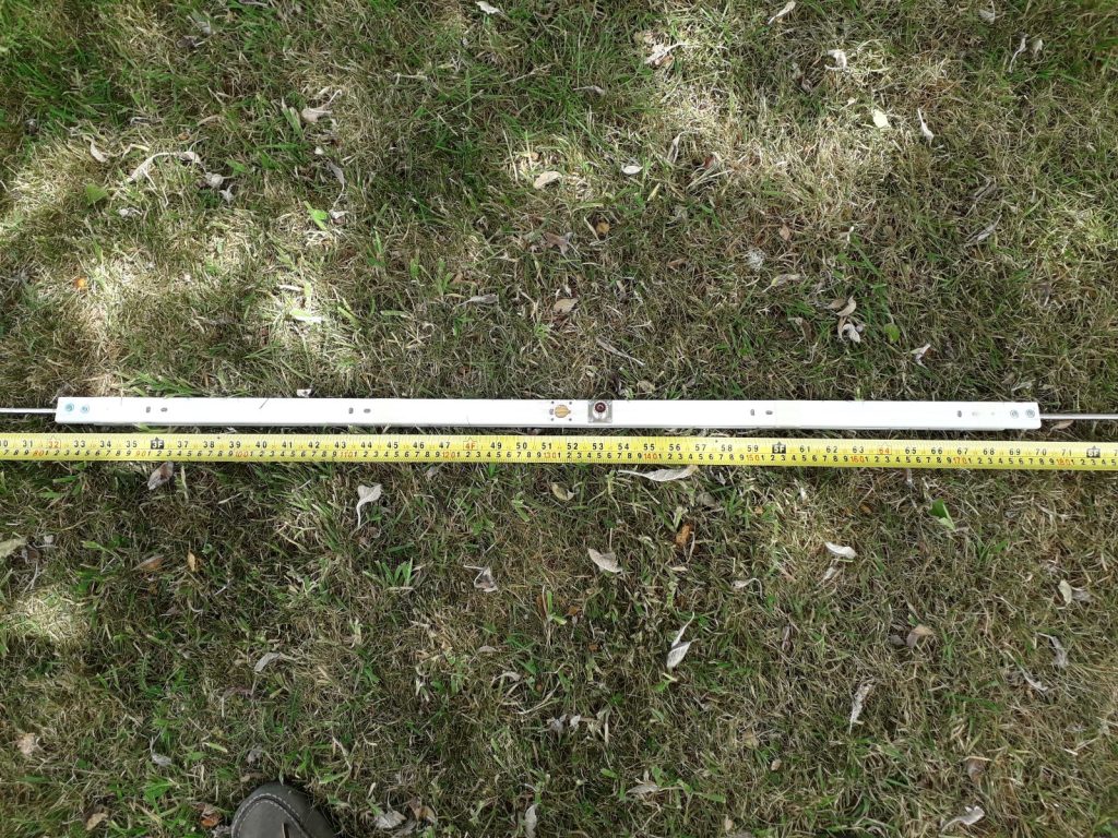
Each telescopic antenna plus conduit was set to a total length of 132cm. Resonance was measured with an MFJ antenna analyser. Resonance occurred at 50.141MHz with an SWR of 1:1.3, Impedance of 41ohms and a Reactance of 8. These interim results were considered sufficiently encouraging to proceed with further construction. The impedance was expected to change with antenna height and the SWR expected to fall.
Time for some carpentry to make an antenna centre fixing panel to attach the dipole antenna to a roach pole, bamboo pole or telescopic aluminium decorator’s pole. Some of the authors favourite ‘sky hooks’!
The fixing panel was designed to add strength to the plastic conduit and to enable both horizontal and vertical polarization of the dipole. Note the 6 holes in the fixing panel for the ‘U’ bolts, which enable either horizontal or vertical orientation of the antenna.
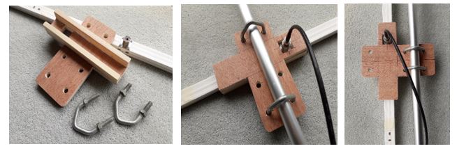
Finally, the conduit was attached to the centre fixing panel using bolts, washers, nuts and glue. The plastic conduit back cover was secured with screws only, allowing future access to wiring.
Into the garden where the completed antenna was clamped to a 3m bamboo pole using 2 ‘U’ bolts and tested once again. The MFJ Analyser was connected via a 3m length of 50 ohm coaxial cable, without the use of a balun.
As expected, at half a wavelength high on 6m, the SWR improved with height; the small change in impedance was considered quite acceptable.
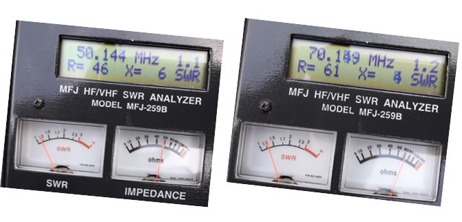
For 50MHz, the length of each dipole leg was finalised at 132cm (52ins). SWR = 1 : 1.1
For 70MHz, the length of each dipole leg was finalised at 91cm (36ins). SWR = 1 : 1.2
Time to find a good elevated location for the antenna and make some 50MHz QSOs …….